Adaptive antenna radio communication device

Active Publication Date: 2005-11-10
PANASONIC INTELLECTUAL PROPERTY CORP OF AMERICA
View PDF14 Cites 29 Cited by
  • Summary
  • Abstract
  • Description
  • Claims
  • Application Information

AI Technical Summary

Benefits of technology

[0009] In case of directivity transmission, an angle spread based on a spatial spectrum is detected in the respective divided bands or the entire communication band. When the angle spread is small, a transmission directivity control is performed on the basis of the average direction-of-arrival of the entire sub-carrier signals. On the other hand, when the angle spread is large, a directivity transmission control is performed either 1) in the direction giving the maximum received power among the direction estimation results in the respective divided bands or 2) in the direction giving the upper received power having the predetermined number among the direction estimation results in the respective divided bands. Thus, a directivity transmission can be made in the direction of arrival path upon reception and interference with other users can be effectively reduced, thus enhancing the communication quality and improving the system capacity.
[0035] According to the present invention, as described above, even when an adaptive antenna radio communication device equipped with an array antenna employs a wideband multi-carrier transmission method and sub-carriers having low received power exit, the deterioration of the estimation accuracy can be suppressed and the reception quality can be improved. Furthermore, in case of a directivity transmission, multiuser interference can be reduced and an improvement of the communication quality can be devised.

Problems solved by technology

Signals received by a radio communication device have been interfered by various signals, leading to the deterioration of the reception quality.
However, the conventional adaptive antenna radio communication device has a problem in that it was unable to estimate the direction with sufficient accuracy for receiving sub-carriers having low received power, when it was influenced by frequency selective fading for performing the direction estimation for each sub-carrier and calculating a weight of a receive array.
Furthermore, it has a problem in that, when the number of sub-carriers was high, the circuit specification has increased.

Method used


Image

  • Adaptive antenna radio communication device
  • Adaptive antenna radio communication device
  • Adaptive antenna radio communication device

Examples


1st exemplary embodiment

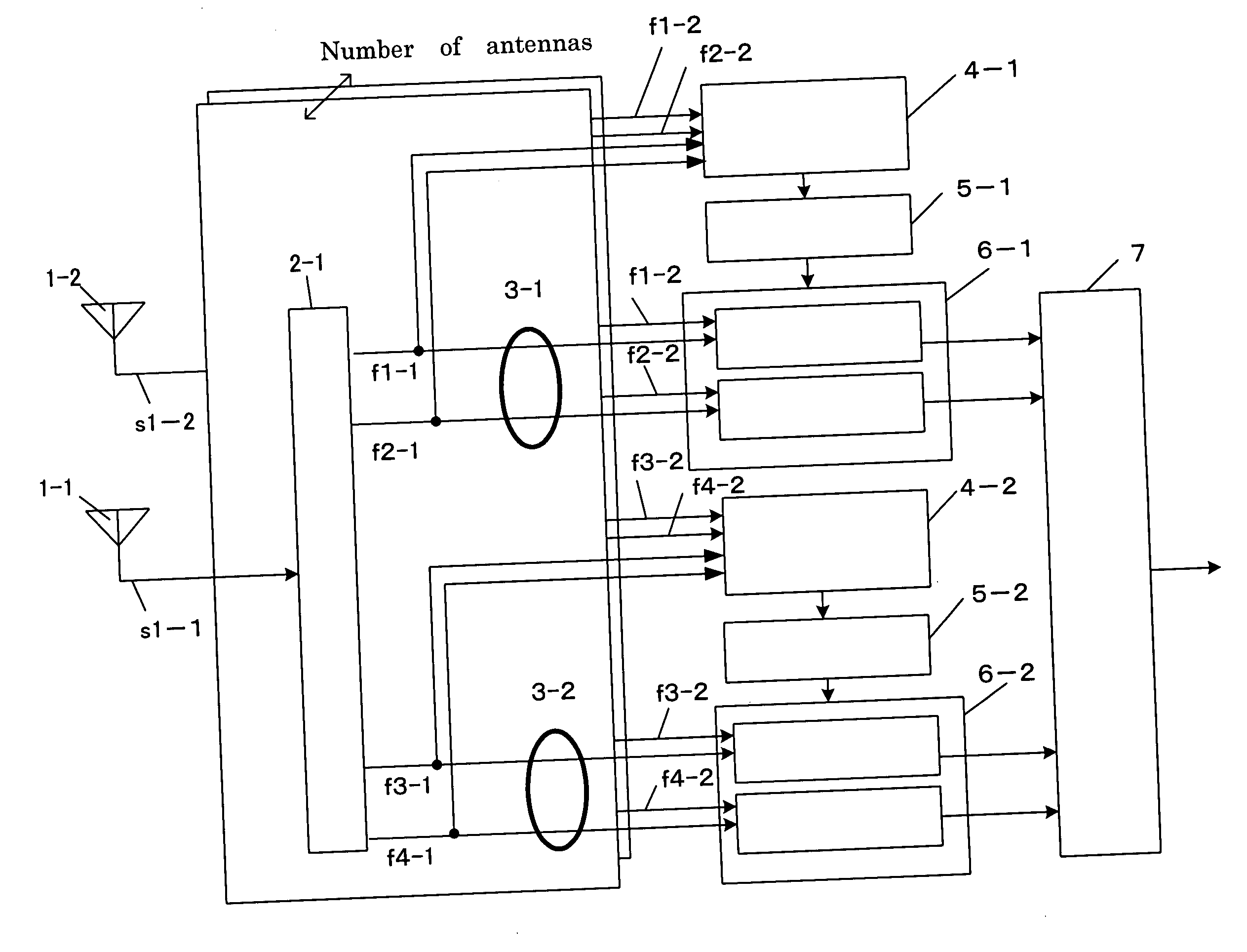
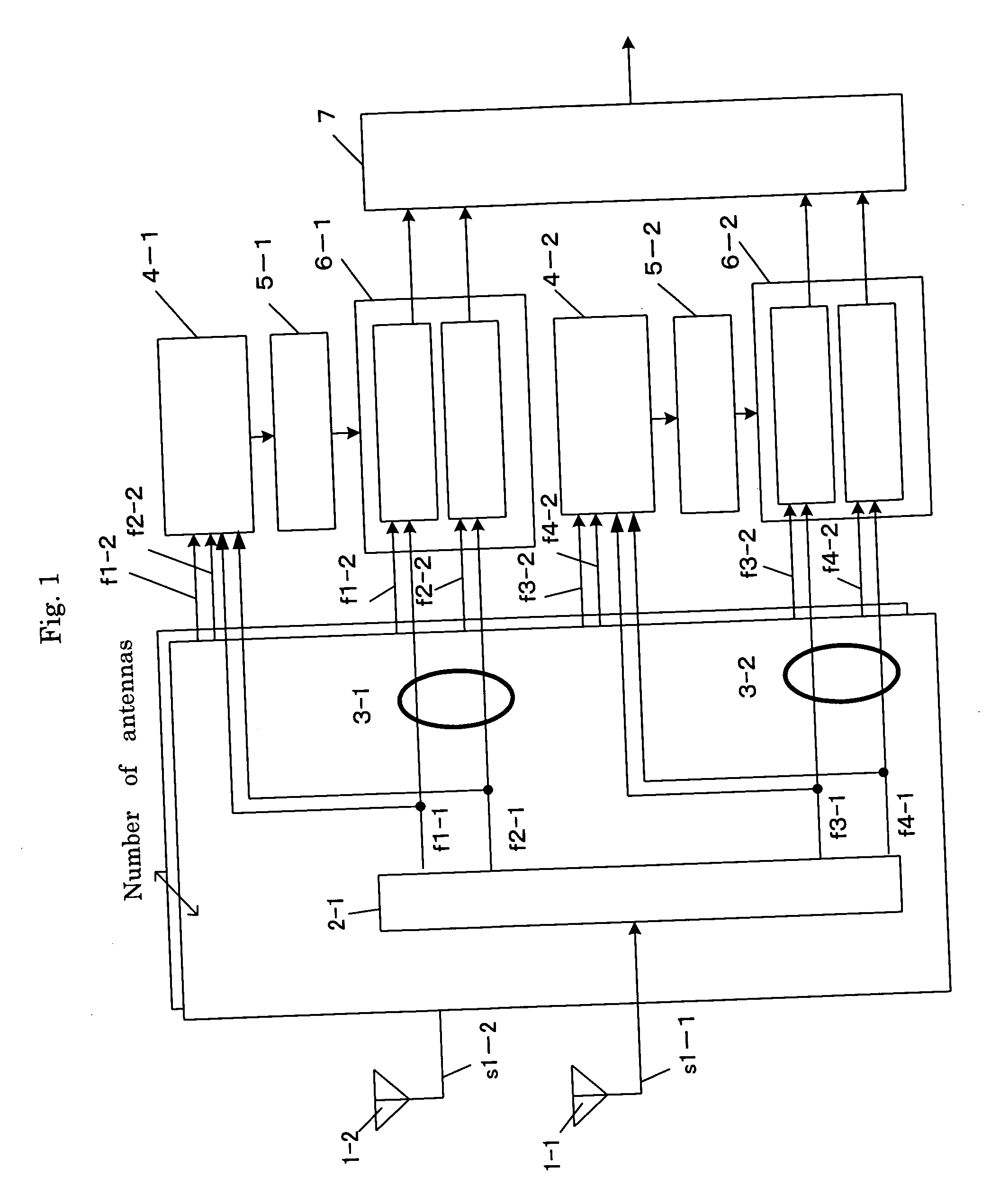
[0044]FIG. 1 is a block diagram illustrating a configuration of an adaptive antenna radio communication device in a first embodiment of the present invention. The adaptive antenna radio communication device illustrated in FIG. 1 comprises an array antenna 1 made up of multiple Na antenna elements 1-1 to 1-Na; a demultiplexer 2-k (however, k is 1 to Na) for demultiplexing a signal s1-k received by a k-th antenna element 1-k to a plurality of Ns sub-carrier signals fl-k to Ns-k after the high frequency signal is frequency-converted; a divided band direction estimating unit 4-m for estimating the direction-of arrival using sub-carrier signals belonging to the m-th divided band 3-m among divided bands in which a communication band is divided into Nd bands; a divided band array weight creating section 5-m for creating a weight of a receive array based on the direction estimation result from the m-th divided band direction estimating unit 4-m; a sub-carrier directivity creating unit 6-m f...


PUM


Abstract

An adaptive antenna radio communication device comprises a divided band direction estimating unit (4) for estimating the direction by calculating the cross correlations between a pilot signal and sub-carrier signals of the respective divided bands received by an array antenna (1) and calculating a spatial profile from correlation matrices determined by combining the correlation values between antenna elements of the different sub-carriers according to the output of the cross correlation calculation; a divided band array weight creating unit (5) for creating a weight of a receive array having a directional beam in the direction of estimation for each divided band; and a sub-carrier directivity creating unit (6) for creating a directivity by multiplication-combining the created receive array weight with the corresponding sub-carrier signal.

Description

TECHNICAL FIELD [0001] The present invention relates to an adaptive antenna radio communication device provided with a direction estimating unit of arrival paths and an array antenna having a directivity controlling unit based thereon for a digital radio communication system in a multi-carrier transmission method using a plurality of sub-carriers having different frequencies. BACKGROUND ART [0002] Signals received by a radio communication device have been interfered by various signals, leading to the deterioration of the reception quality. As a technique to suppress this kind of interference and strongly receive only signals arriving from a desired direction, an adaptive array antenna (adaptive antenna) has been known. The adaptive array antenna can receive only signals arriving from a desired direction by adjusting a weight coefficient by which the receiving signals are multiplied (hereinafter, the weight coefficient is referred to as “weight”) to adjust the amplitude and phase giv...

Claims


Application Information

Patent Timeline
IPC IPC(8): H04B7/08H04B7/10H04B7/12H04J11/00H01Q3/26H04J13/00H04L27/26
CPCH04B7/086G01S3/14G01S3/043H04L27/2601
Inventor KISHIGAMI, TAKAAKIFUKAGAWA, TAKASHIYUDA, YASUAKITAKAKUSAKI, KEIJIMIYAMOTO, SHOJI
Owner PANASONIC INTELLECTUAL PROPERTY CORP OF AMERICA
Why Eureka
Try Eureka