
Apparatus for determining concentrations of light absorbing substances in blood

Active Publication Date: 2005-11-10
NIHON KOHDEN CORP
View PDF5 Cites 66 Cited by
  • Summary
  • Abstract
  • Description
  • Claims
  • Application Information

AI Technical Summary

Benefits of technology

[0035] It is therefore an object of the invention to provide an apparatus for determining concentrations of light absorbing substances in blood, which enables substantial reduction in power consumption without causing a decrease in measurement accuracy.
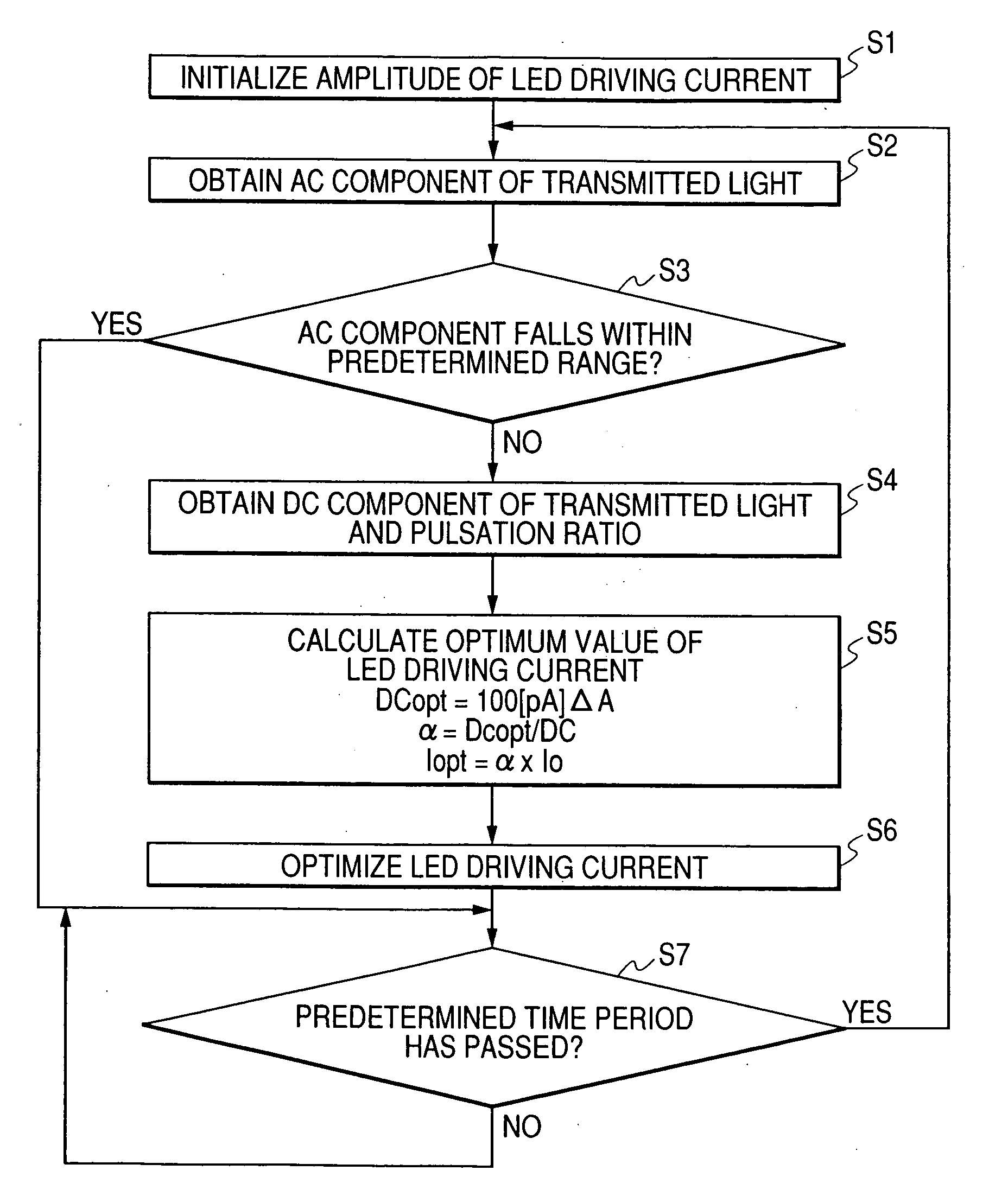
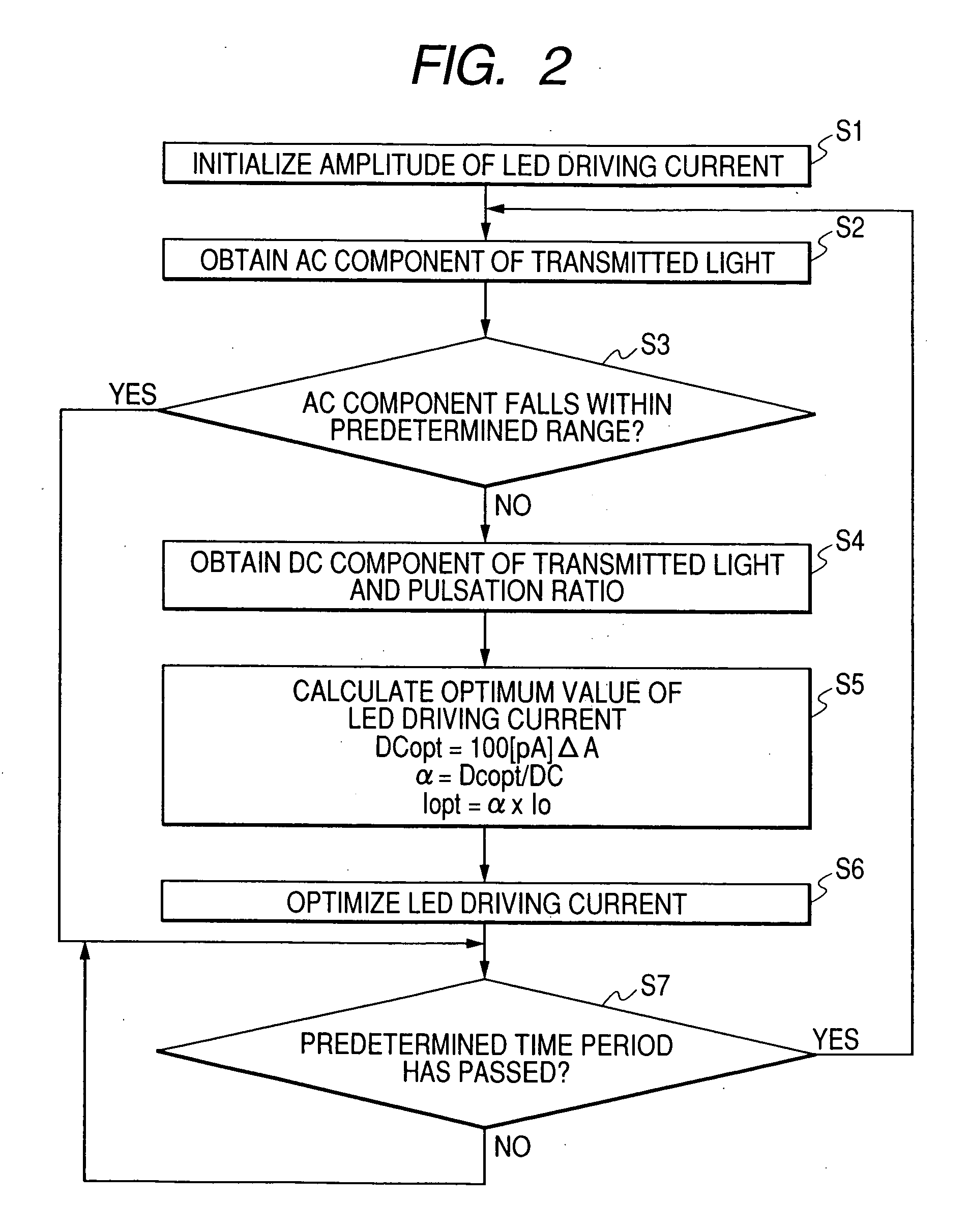
[0045] In other words, by adding a function of controlling current values for driving the photo emitters such that an AC component value of light transmitted through a patient falls within a predetermined range, driving minimum current values optimal to an individual patient can be obtained in accordance with the condition of the patient. Accordingly, there can be realized an apparatus for determining concentrations of light absorbing substances in blood which enables substantial reduction in power consumption without causing decrease in measurement accuracy.

Problems solved by technology

The same problem described above applies to other apparatus for determining concentrations of light absorbing substances in blood, such as hemoglobin concentration, dye concentration, bilirubin concentration, and blood glucose level.
However, in a case of a patient whose pulse wave is small, the AC component is small even when the DC component is large.
Accordingly, when the amount of light emitted from the LED section 1 is reduced, detection of the AC component which can maintain measurement accuracy as a pulse oximeter becomes difficult.
In this case, there arises a problem that, since an LED current larger than required is supplied to a patient having a large AC component, sufficient control for power-saving cannot be achieved.
As mentioned above, the control that focuses attention solely on the DC component enables reduction of the LED driving current from the point “a” to the point “b.” In spite of this fact, an LED driving current of 1,000 (nA) or higher is achieved at all times. Hence, difficulty is encountered in substantially saving power.

Method used


Image

  • Apparatus for determining concentrations of light absorbing substances in blood
  • Apparatus for determining concentrations of light absorbing substances in blood
  • Apparatus for determining concentrations of light absorbing substances in blood

Examples


Embodiment Construction

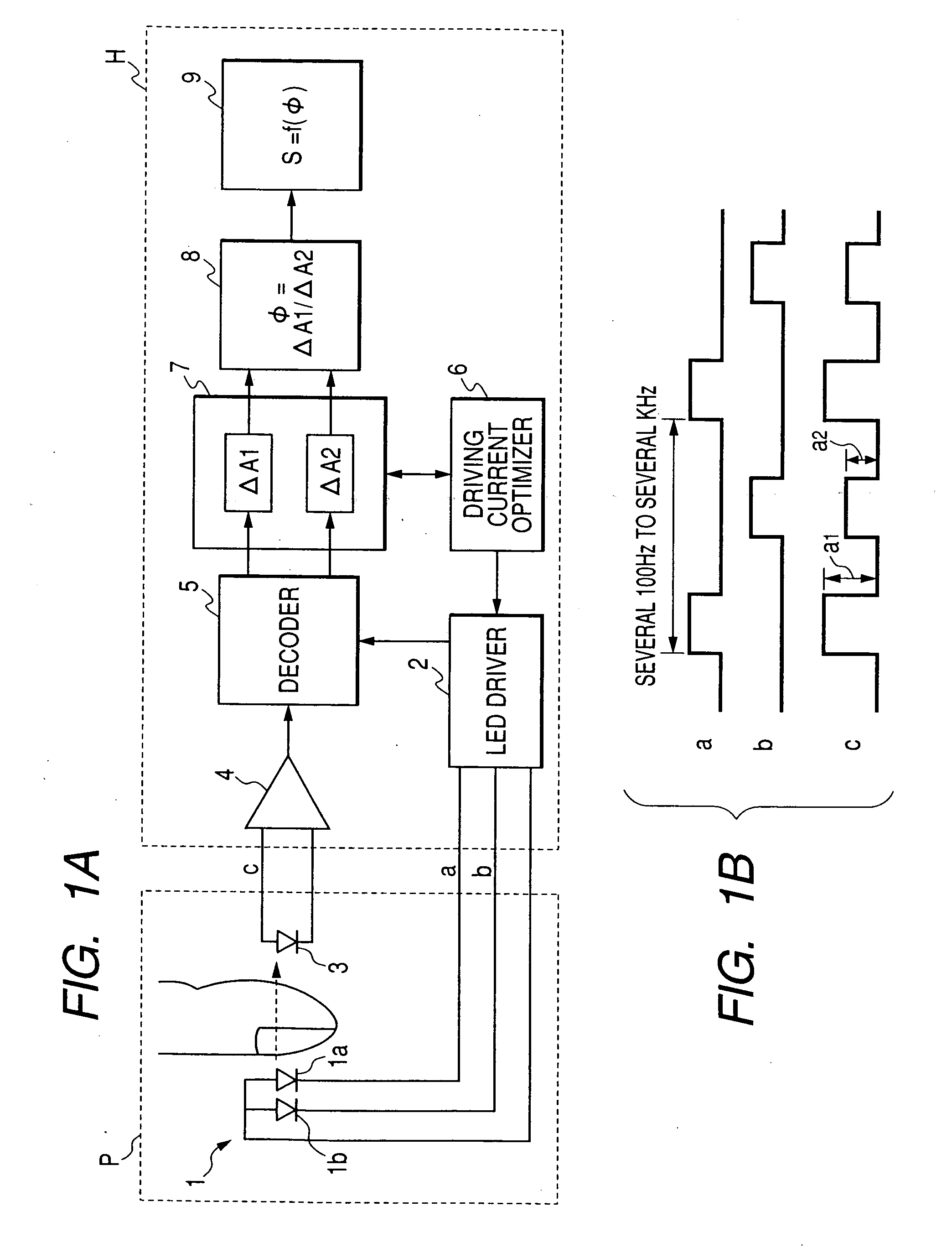
[0055] Embodiments of the invention will be described below in detail with reference to the accompanying drawings. In FIGS. 1A and 1B, a pulse oximeter is taken as an example of an apparatus for determining concentrations of light absorbing substances in blood of the invention. The same component as those in the conventional pulse oximeter shown in FIG. 5 will be designated by the same reference numeral, and repetitive explanations for those will be omitted.

[0056] In this embodiment, in order to attain substantial reduction in power consumption without causing a decrease in measurement accuracy, the Driving current optimizer 6 is provided. The Driving current optimizer 6 receives data on a DC component of transmitted light, an AC component of the transmitted light, and pulsation ratio output from the pulsation ratio detector 7; and controls current supplied from the LED driver 2 to the LED section 1. Accordingly, the AC component of the transmitted light reaches a predetermined val...


PUM


Abstract

In an apparatus for determining a concentration of a light absorbing substance in blood, a plurality of photo emitters are adapted to emit light beams having different wavelengths toward a living tissue including a blood vessel. A photo receiver is adapted to receive the light beams which have been transmitted through or reflected from the living tissue. A driver inputs driving currents for causing the respective photo emitters to emit the light beams. An optimizer obtains values of AC components of the light beams received by the photo receiver, and adjusts values of the driving currents such that the values of the AC components fall within a predetermined range.

Description

BACKGROUND OF THE INVENTION [0001] The present invention relates to an improvement of an apparatus which irradiates light on living tissue of a patient, and detects light transmitted through or reflected by the living tissue, thereby determining concentrations of light absorbing substances in blood. [0002] Pulsating components of light transmitted through or reflected by living tissue include information on light absorption characteristics of light absorbing substances in blood. [0003] Accordingly, by measuring pulsating components of light transmitted through or reflected by living tissue with use of a plurality of wavelengths, ratios between concentrations of a plurality of light absorbing substances in blood can be measured. [0004] This basic principle has a wide range of applications, and is given the generic name of pulse photometry. One application of the principle is a pulse oximeter which determines arterial oxygen saturation continuously in a noninvasive manner. [0005] Sinc...

Claims


Application Information

Patent Timeline
IPC IPC(8): A61B5/00A61B5/0245A61B5/145A61B5/1455G01N21/35G01N21/359
CPCA61B5/14532A61B2560/0209A61B5/14551
Inventor TAKEDA, SUNAOKOBAYASHI, NAOKIKUBOTA, HIROSHI
Owner NIHON KOHDEN CORP
Learn More