
Methods of and apparatus for forming hollow metal articles

a technology of hollow metal and forming apparatus, which is applied in the direction of transportation and packaging, transportation items, other domestic objects, etc., can solve the problems of not achieving such configurations in conventional can-producing operations, and achieve the effect of avoiding workpiece failur

Active Publication Date: 2005-11-17
MONTEBELLO PACKAGING A DIVISION OF GREAT PACIFIC ENTERPRISE INC
View PDF27 Cites 30 Cited by
  • Summary
  • Abstract
  • Description
  • Claims
  • Application Information

AI Technical Summary

Benefits of technology

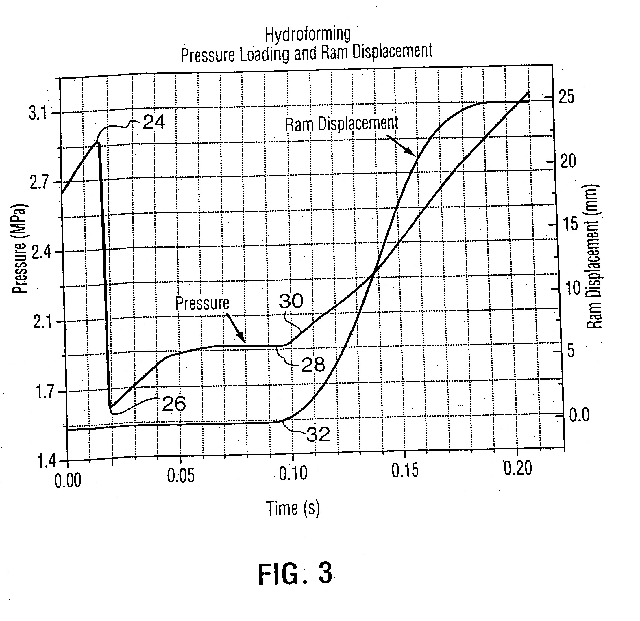
"The present invention provides a method for optimizing the pressure-time history for a process of forming a hollow metal article from a preform by subjecting it to net internal fluid pressure. The method involves selecting a set of process parameters and determining a failure criterion limiting the pressure-time conditions to which the workpiece can be subjected without failure. The failure criterion can be minimum wall thickness, strain, or strain rate. The method then performs finite element analyses on the workpiece at different values of pressure and time to determine the pressure-time boundary conditions. These boundary conditions can be used to create an optimized pressure-time history for the process. The invention also includes a computer program for implementing the method. The technical effect of the invention is to improve the process of forming hollow metal articles by controlling the pressure-time history and avoiding failure of the workpiece during the process."

Problems solved by technology

Conventional can-producing operations, however, do not achieve such configurations.

Method used


Image

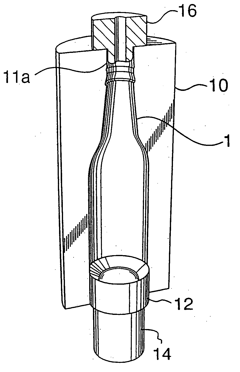
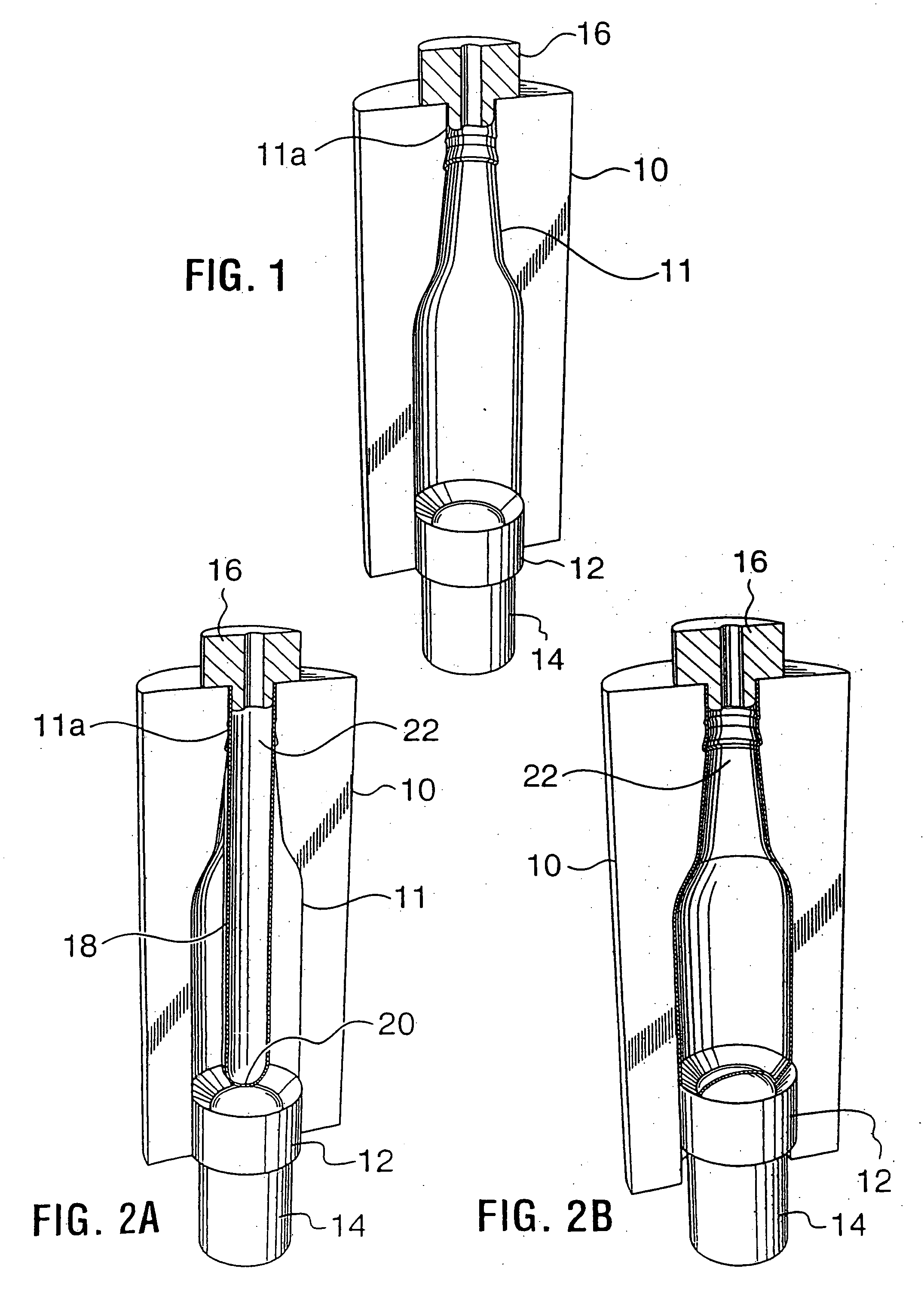
  • Methods of and apparatus for forming hollow metal articles
  • Methods of and apparatus for forming hollow metal articles
  • Methods of and apparatus for forming hollow metal articles

Examples


second embodiment

[0078] the PRF method of the aforesaid copending application is illustrated in FIGS. 4A-4D. In this embodiment, as in that of FIGS. 2A and 2B, the cylindrical preform 38 has an initial outside diameter equal to the minimum diameter (neck) of the final product. However, in this embodiment it is assumed that the forming strains of the PRF operation exceed the formability limits of the preform. In this case, two sequential pressure forming operations are required. The first (FIGS. 4A and 4B) does not require a ram and simply expands the preform within a simple split die 40 to a larger diameter workpiece 38a by internal pressurization. The second, a PRF procedure (FIGS. 4C and 4D), starts with the workpiece as initially expanded in the die 40 and, employing a split die 42 with a bottle-shaped cavity 44 and a punch 46 driven by a ram 48, i.e., using both internal pressure and the motion of the ram, produces the final desired bottle shape, including all features of the side-wall profile a...

third embodiment

[0079] A third embodiment is shown in FIGS. 5A and 5B. In this embodiment, the preform 50 is made with an initial outside diameter that is greater than the desired minimum outside diameter (usually the neck diameter) of the final bottle-shaped container. This choice of preform may result from considerations of the forming limits of the pre-forming operation or may be chosen to reduce the strains in the PRF operation. In consequence, manufacture of the final product must include both diametrical expansion and compression of the preform and thus can not be accomplished with the PRF apparatus alone. A single PRF operation (FIG. 5A, employing split die 52 and ram-driven punch 54) is used to form the wall and bottom profiles (as in the embodiment of FIGS. 2A and 2B) and a spin forming or other necking operation is required to shape the neck of the container. As illustrated in FIG. 5B, one type of spin forming procedure that may be employed is that set forth in U.S. Pat. No. 6,442,988, th...


PUM

PropertyMeasurementUnit
temperatureaaaaaaaaaa
compressiveaaaaaaaaaa

Abstract

In hydroforming of hollow metal articles in a die, such as pressure-ram-forming procedures, a method of decreasing cycle time of the forming process, while ensuring acceptable product properties and avoiding failures, by modeling the process using finite element analysis to establish a pressure-time history that optimizes the forming operation and applies failure limits to selected variables such as minimum wall thickness or maximum strain rate, and transferring this pressure-time history to a computer controlling the forming process. Thermocouple and / or continuity sensors are incorporated into the die wall and connected to the computer so as to provide active feedback from the die to the control of the process.

Description

CROSS REFERENCE TO RELATED APPLICATION [0001] This application claims the priority benefit, under 35 U.S.C. §119(e), of U.S. provisional patent application No. 60 / 571,472 filed May 14, 2004, the entire disclosure of which is incorporated herein by this reference.BACKGROUND OF THE INVENTION [0002] This invention relates to methods of and apparatus for forming hollow metal articles utilizing internal fluid pressure to expand a hollow metal preform or workpiece against a die cavity, and especially to pressure-ram-forming methods and apparatus and the like. In an important specific sense, the invention is directed to methods of and apparatus for forming aluminum or other hollow metal articles having a contoured shape, e.g. such as a bottle shape with asymmetrical features. For purposes of illustration particular reference will be made herein to forming metal containers, but the invention in its broader aspects is not limited thereto. [0003] Metal cans are well known and widely used for ...

Claims


Application Information

Patent Timeline
Patent Type & Authority Applications(United States)
IPC IPC(8): B21D22/00B21D26/047B21D26/049B21D51/24
CPCB21D26/033B21D26/041B21D51/26B21D26/049B21D26/047
Inventor MACEWEN, STUART R.HAMSTRA, PETERMALLORY, ROBERT WILLIAMSHI, YIHAIMOULTON, JAMES D.
Owner MONTEBELLO PACKAGING A DIVISION OF GREAT PACIFIC ENTERPRISE INC
Learn More