Boat lift canopy assembly

a technology of canopy cover and assembly, which is applied in the direction of vessel construction, building types, construction, etc., can solve the problems of reducing the aesthetic appeal of the cover, affecting the aesthetics of the wrapped canopy cover and the integrity of the fabric, and being expensive and often impractical

Inactive Publication Date: 2005-11-17
IPO
View PDF6 Cites 29 Cited by
  • Summary
  • Abstract
  • Description
  • Claims
  • Application Information

AI Technical Summary

Benefits of technology

[0014] The present invention is a boat lift canopy, comprising a truss type framework with a base frame that may be rectangular. Joined to the base frame and circumscribed by it is a tie tube frame, which may be discontinuous. A fabric cover, which in preferred embodiments is decorative as well as finctional, snugly encloses the outside of the framework, wraps around the base frame and is secured to the tie tube frame. The boat lift canopy is held above the boat lift by vertical members, which in some embodiments are vertical extensions of the legs of the boat lift. Advantageously, the canopy is releasably coupled to the vertical members at the tie tube frame, thereby enabling simple adjustment of the position of the canopy with respect to the vertical members, permitting adjustment of canopy overhang or length with ease. Embodiments of the canopy allow adjustment of the length of the canopy by the addition of frame members extending the canopy framework, such adjustment facilitated by the releasable coupling of the canopy to the vertical members. The framework of the canopy employs an improved truss design such as Howe Kingpost to maximize framework strength, thereby enhancing endurance of the canopy and permitting substantial cantilevered canopy overhangs.

Problems solved by technology

While boat houses can provide such shelter, they are expensive and often impractical.
Unless, however, screws or bolts securing the base members to the legs are counter-sunk in some manner, their ends present protrusions in the surface of the member, to the detriment of both the aesthetics of the wrapped canopy cover and the integrity of its fabric.
Limiting the cover so that it does not wrap around the member at leg junctions, as when the members are welded to the legs, has the result either of requiring specially tailored, non-rectangular covers, at considerable expense, or permitting only incomplete wrapping of the base members with the cover fabric, reducing the aesthetic appeal of the cover.
If, on the other hand, the cover is wrapped between the member and the leg, a screw, bolt or similar fastener joining the leg to the member must pass through the cover fabric, diminishing the integrity of the fabric and preventing removal or replacement of the cover without disassembling the canopy from the legs.
A further limitation of the prior art boat lift canopy is that it is often desirable to change the length of a canopy, as when, for example, the lift is used for a boats of a different length.
As is clear from the foregoing description, however, the prior art canopy is not easily moved with respect to the legs.
In the case of canopies secured to the legs by welding, it often is simply not possible at all to move the canopy with respect to the legs after the canopy is attached.
A further limitation of the prior art boat lift canopy is that, in general, it is not designed to maximize the structural integrity possible in truss type framework structures.
Long unsupported overhangs, which have become increasingly popular, require that the canopy possess considerable structural strength and rigidity.
However, many prior art canopies simply do not possess sufficient strength for long cantilevered overhangs.

Method used


Image

  • Boat lift canopy assembly
  • Boat lift canopy assembly
  • Boat lift canopy assembly

Examples


Embodiment Construction

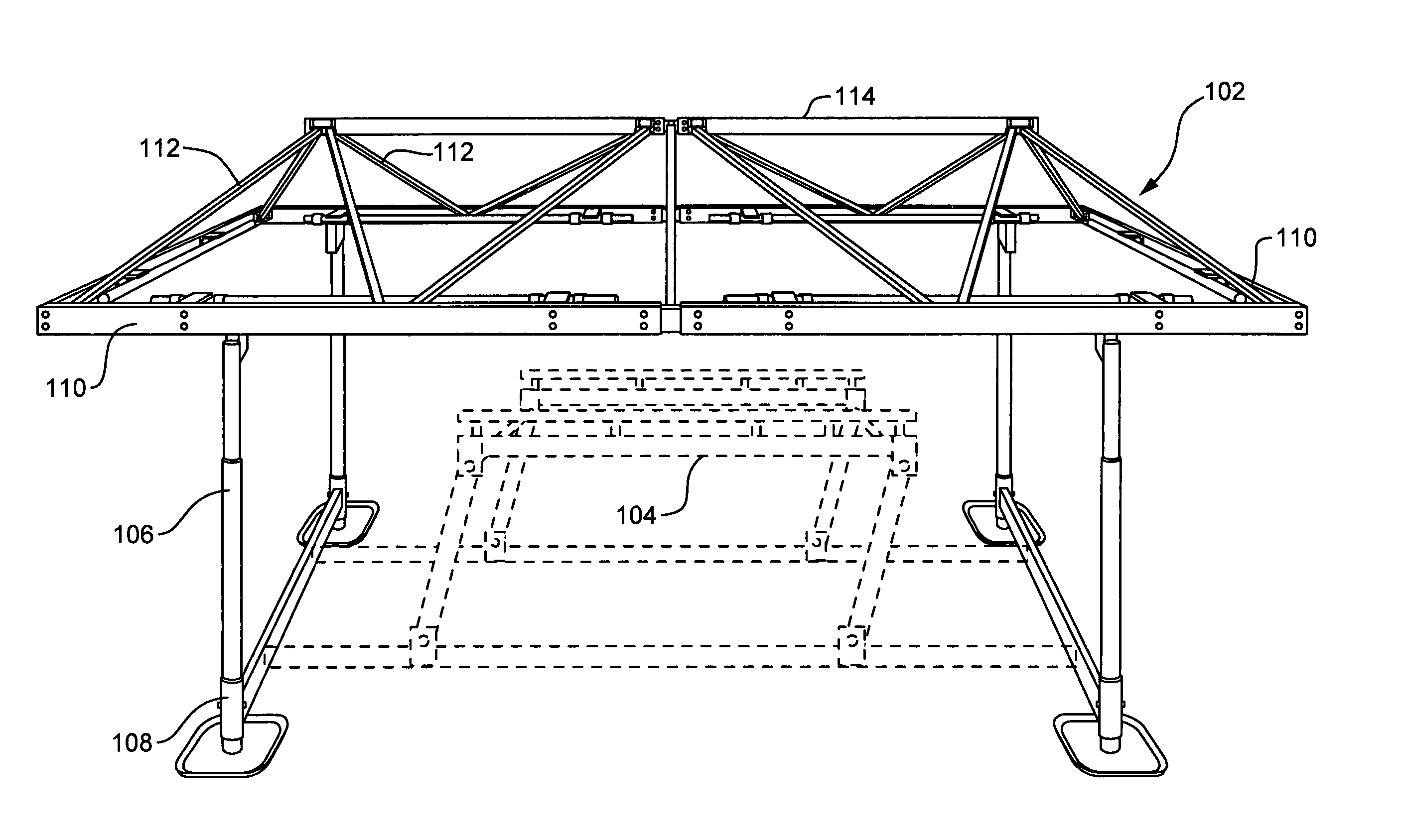
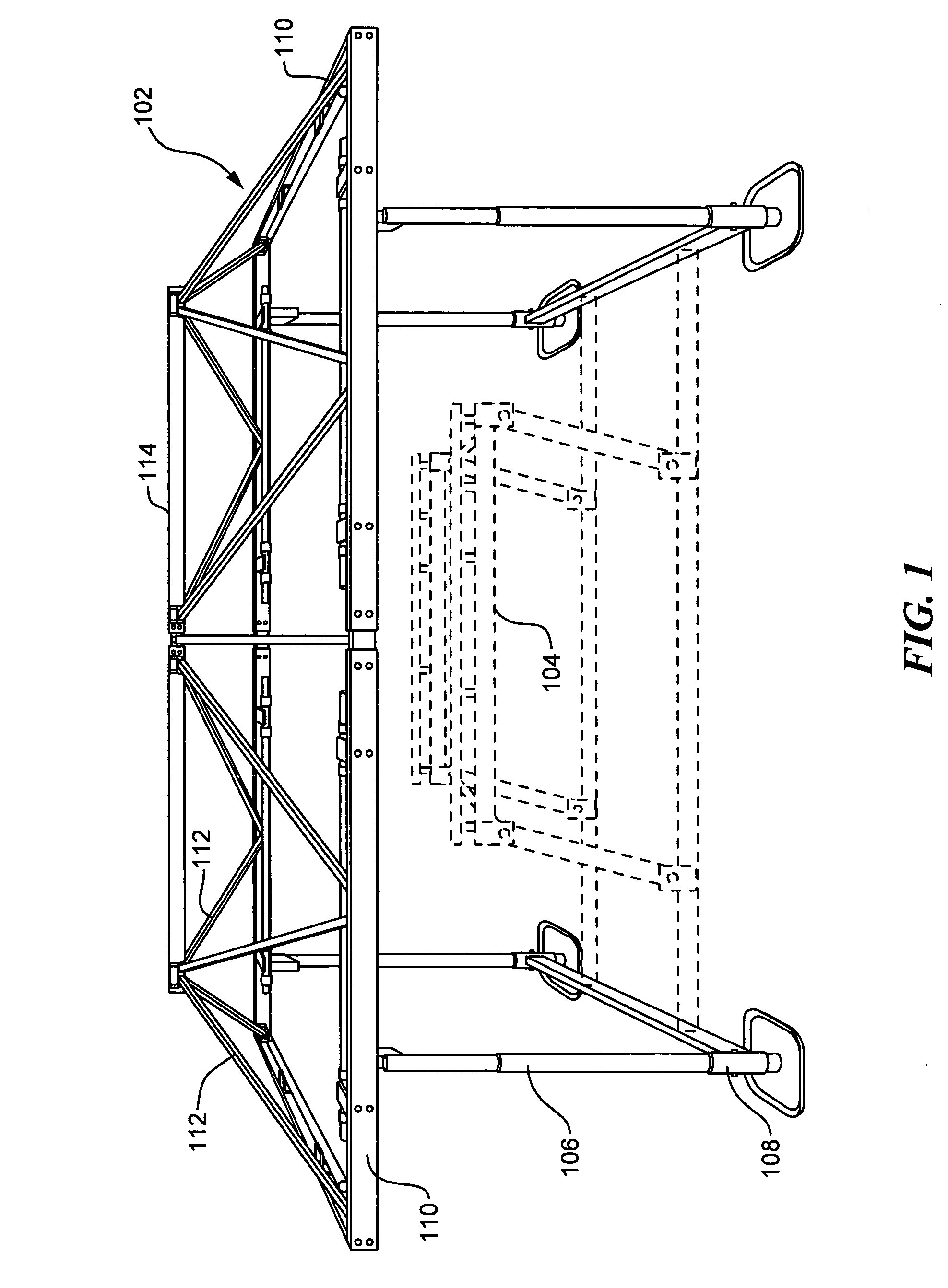
[0023] Turning now to FIG. 1, depicted is an embodiment of the present invention. Canopy 102 sits over a watercraft lift 104. Lift 104 may be any form of watercraft lift designed to be affixed to the bottom of a body of water, such as described in U.S. Pat. No. 5,908,264 to Hey or U.S. Pat. No. 5,184,914, issued to the inventor of the present invention and which is incorporated herein by reference. Alternatively, lift 104 may be a floating lift as described in U.S. Pat. No. 5,485,798 to Samoian et al., or U.S. patent application Ser. No. 10 / 816,992 by the inventor of the present invention, incorporated herein by reference.

[0024] Canopy 102 is suspended above lift 104 by upright members 106. Lifts affixed to the bottom of the body of water, such as '264 and '914 cited above, generally sit upon legs 108, and in such case upright members 106 may simply be vertical extensions of legs 108. Alternatively, members 106 may be affixed to some other part of lift 104, or members 106 themselve...


PUM


Abstract

A boat lift canopy comprises a truss type framework with a base frame. Joined to the base frame and circumscribed by it is a tie tube frame, which may be discontinuous. A fabric cover, which in preferred embodiments is decorative as well as functional, snugly encloses the outside of the framework, wraps around the base frame and is secured to the tie tube frame. The boat lift canopy is held above the boat lift vertical members, which in some embodiments are vertical extensions of the legs of the boat lift. Advantageously, the canopy is releasably coupled to the vertical members at the tie tube frame, thereby enabling simple adjustment of the position of the canopy with respect to the vertical members, permitting adjustment of canopy overhang or length with ease. Embodiments of the canopy allow adjustment of the length of the canopy by the addition of frame members extending the canopy framework, such adjustment facilitated by the releasable coupling of the canopy to the vertical members. The framework of the canopy employs an improved truss design such as Howe Kingpost to maximize framework strength, thereby enhancing endurance of the canopy and permitting substantial cantilevered canopy overhangs.

Description

BACKGROUND OF THE INVENTION [0001] 1. Field of the Invention [0002] This invention relates to truss type framework canopies to provide shelter for boats. More particularly, this invention relates to an improved canopy structure mounted above a boat lift. [0003] 2. Description of the Related Art [0004] Users of watercraft have need to shelter docked boats from the elements. While boat houses can provide such shelter, they are expensive and often impractical. Users of watercraft also have need to lift their watercraft from the water, for example for maintenance or in preparation for land transportation of the watercraft, along with a need to lower their watercraft into the water, for example for launching or simply for flotation at dock. Answering such needs, the prior art has provided lift devices employed to raise and lower watercraft with canopies to protect the watercraft from the elements while the watercraft is docked at or engaged by the lift. [0005] Typical of boat lift canopi...

Claims


Application Information

Patent Timeline
Patent Type & Authority Applications(United States)
IPC IPC(8): B63B17/02B63C5/00E04H15/34E04H15/42
CPCB63B17/02E04H15/34B63C5/00
Inventor BASTA, SAMUEL T.
Owner IPO
Why Eureka
Try Eureka