Dual clutch assembly for a motor vehicle powertrain

a technology of clutches and motor vehicles, applied in the direction of mechanical actuated clutches, friction linings, couplings, etc., can solve the problems of increasing the deflection of the crankshaft and increasing the system load, increasing the deflection of the crankshaft and resulting load, and irregular wear of the friction discs of the clutch, so as to reduce the imbalance forces of first order, improve the noise, vibration and harshness of the powertrain, and support the clutch system

Inactive Publication Date: 2005-11-17
FORD GLOBAL TECH LLC
View PDF3 Cites 22 Cited by
  • Summary
  • Abstract
  • Description
  • Claims
  • Application Information

AI Technical Summary

Benefits of technology

[0009] In the clutch assembly according to this invention, the entire clutch system mass is fully supported by two bearings mounted on the transmission housing. This mounting technique provides a stable support for the clutch system free from the effects of crankshaft whirl and misalignment of the crankshaft relative to the transmission. Powertrain noise, vibration and harshness is improved due to the reduction in first order imbalance forces.
[0011] In one embodiment, two axially spaced bearings that support the clutch mass on the transmission housing are located on an axial side of the clutch near the housing. In this way, the clutch mass is provided with two axially spaced bearings that rotatably support the clutch mass, which is overhung from those spaced bearings. In another embodiment, the rotating clutch mass is provided again with two axially spaced supports. One support is a bearing mounted on the transmission housing at one axial side of the clutch center of mass. The other support is a radial disc piloted on a surface of the crankshaft and located at the opposite side of the center of mass from the location of the bearing support. Neither technique for supporting the clutch mass requires the center of mass to be cantilevered from the transmission housing or from the engine crankshaft, thereby preventing the orbiting eccentricity that a cantilevered support arrangement produces.

Problems solved by technology

The resulting orbiting radius from the crankshaft axis and the clutch mass together induce a first order forced vibration in the powertrain, which further increases crankshaft deflection and increases load on the system.
Misalignment of the engine crankshaft centerline relative to the transmission input shaft centerline causes the surfaces of the friction discs of the clutch to wear irregularly in compliance with the misalignment.
Misalignment of the clutch mass relative to the crankshaft during initial installation also contributes to the problem.
The resulting orbit radius and the torque converter mass induce a first order vibration in the powertrain, which increases the crankshaft deflection and resulting loads.
Misalignment of the torque converter mass relative to the crankshaft during installation and misalignment of the transmission support relative to the engine crankshaft centerline contribute to the vibration.

Method used


Image

  • Dual clutch assembly for a motor vehicle powertrain
  • Dual clutch assembly for a motor vehicle powertrain
  • Dual clutch assembly for a motor vehicle powertrain

Examples


Embodiment Construction

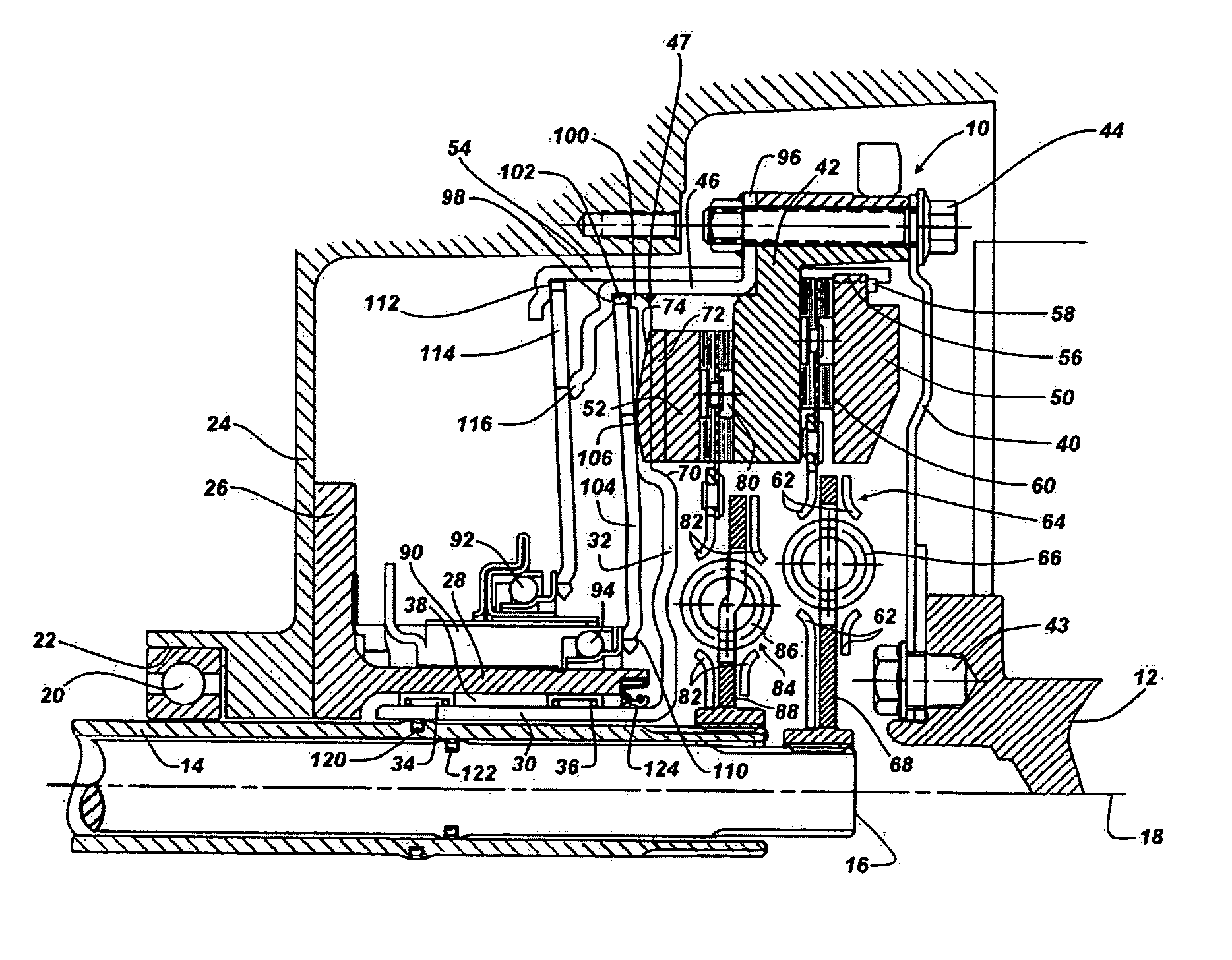
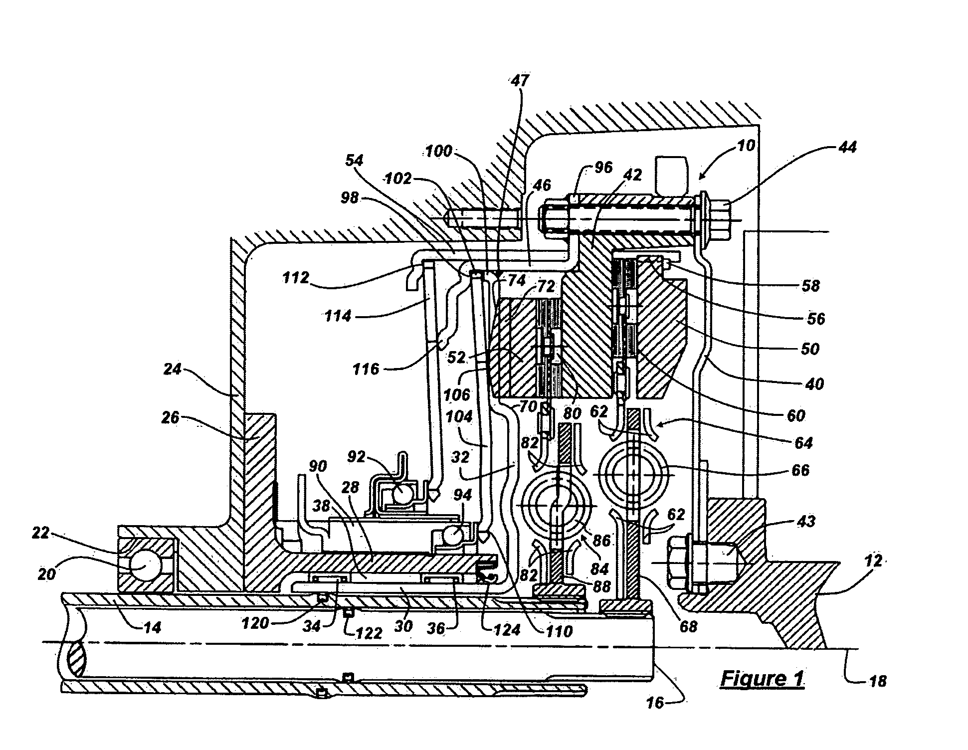
[0016] Referring now to the drawings, there is illustrated in FIG. 1 a dual clutch assembly 10 for transmitting power between an engine crankshaft 12 and first and second input shafts 14, 16 alternately. Shaft 12 may be an output shaft driven by an electric motor or hydraulic motor. Input shaft 14 is a sleeve shaft. Input shaft 16 is a solid shaft coaxial with shaft 12 and located within the sleeve shaft along at least a portion of its length. The input shafts are driveably connected to gearing that produces various ratios of the speed of a transmission output shaft and the speed of the input shafts. The dual clutch assembly and the input shafts are arranged about a longitudinal axis 18.

[0017] The crankshaft 12 is supported for rotation on bearings (not shown) located in the engine block. The input shafts 14, 16 are rotatably supported on a clutch support bearing 20, which is pressed into a recess 22 formed in a transmission housing 24, in which the gearing, shafts, synchronizers a...


PUM


Abstract

A powertrain assembly for transmitting torque between a power source and a transmission includes an input shaft, a housing on which the input shaft is rotatably supported, a flywheel rotatably supported at two axially spaced locations, at least one of the locations providing support for the flywheel on the housing, and a clutch for driveably connecting and disconnecting the flywheel and the input shaft.

Description

BACKGROUND OF THE INVENTION [0001] 1. Field of the Invention [0002] The invention relates to friction clutches. In particular the invention pertains to dual friction clutches for connecting a power source output shaft alternately to input shafts of a motor vehicle transmission. [0003] 2. Description of the Prior Art [0004] Conventional automotive dry clutch systems are supported directly on the engine crankshaft distant from the center of mass of the system. The mass of the clutch system is cantilevered and subject to bending displacement relative to the centerline of the crankshaft. As the crankshaft rotates, the mass of the clutch system is subject to orbiting motion about the true centerline of the crankshaft. The resulting orbiting radius from the crankshaft axis and the clutch mass together induce a first order forced vibration in the powertrain, which further increases crankshaft deflection and increases load on the system. [0005] Misalignment of the engine crankshaft centerli...

Claims


Application Information

Patent Timeline
Patent Type & Authority Applications(United States)
IPC IPC(8): B60K17/00B60K17/08F16D13/58F16D21/02F16D21/06F16F15/131F16F15/315
CPCF16D21/06F16F15/13121F16D2021/0684F16D2021/0607
Inventor VANSELOUS, JOSEPHJANSON, DAVIDHAMMOND, MATTHEWKNOWLES, SHAUNOLENDER, ANDY
Owner FORD GLOBAL TECH LLC
Why Eureka
Try Eureka