
Pneumatic fastener driving system with self-contained gas source

a driving system and self-contained technology, applied in the field of pneumatic tools, can solve the problems of limited length, wear and tear of hoses, restricted distance between tools and air compressors, etc., and achieve the effect of convenient manoeuvr

Inactive Publication Date: 2005-11-17
D & S PROD SOLUTIONS
View PDF29 Cites 27 Cited by
  • Summary
  • Abstract
  • Description
  • Claims
  • Application Information

AI Technical Summary

Benefits of technology

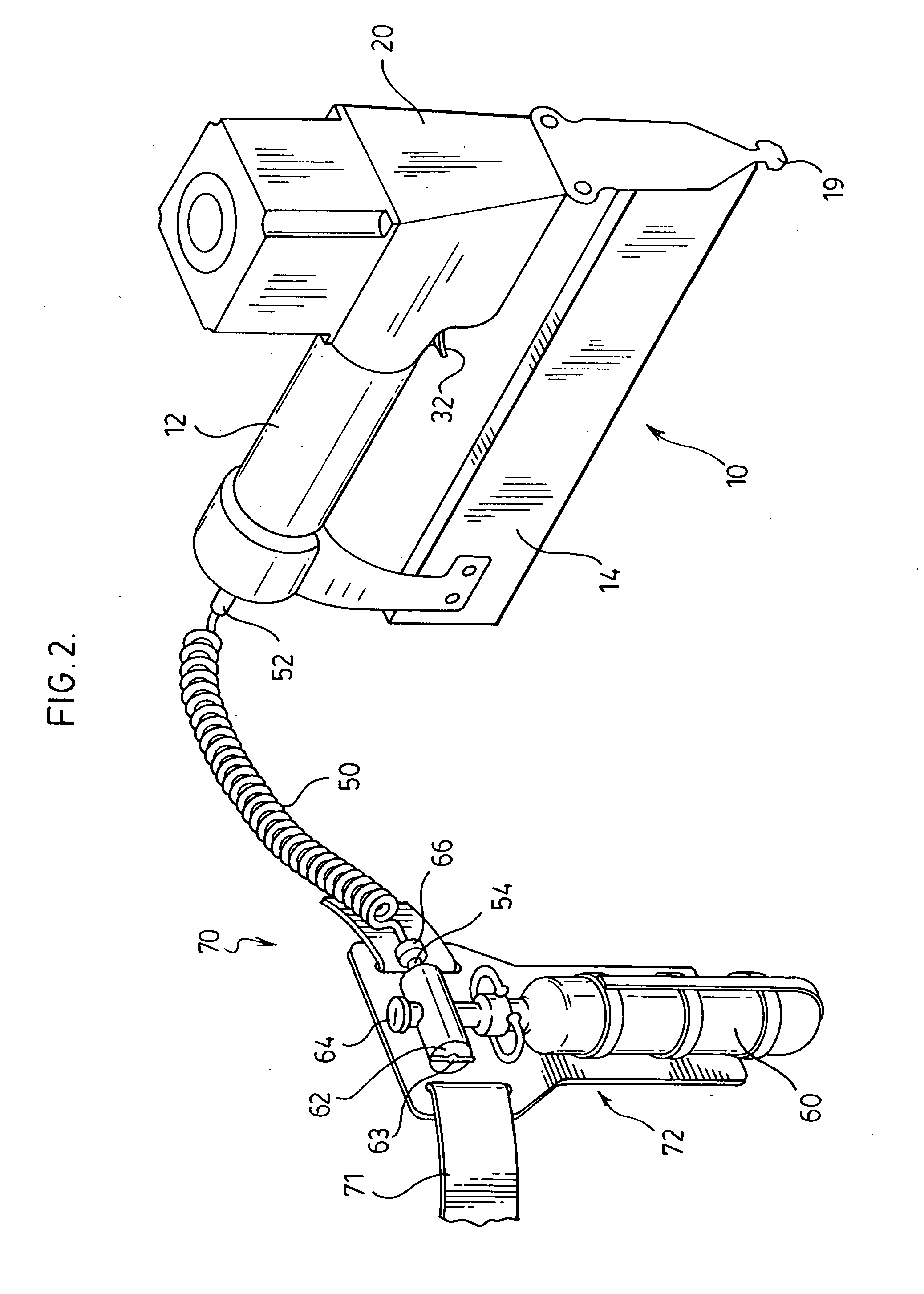
[0008] The present invention provides a self-contained pneumatic fastener driving system comprising a fastener driving tool that operates from a compressed gas canister and a local holder for mounting the gas canister in proximity of the tool. The gas canister is either connected to the tool by a short pneumatic hose, which is light and easy to manoeuvre, or in some preferred embodiments integrated into the driving tool itself. The gas canister provides a source of compressed gas sufficient for hundreds of strokes having the required percussive force to drive a large brad, while not suffering from the constraints of attachment to a bulky air compressor.
[0011] The fastener driving tool of the invention accordingly provides a self-contained, lightweight and easy to manipulate fastener driver that can drive hundreds of fasteners before the gas canister needs to be changed or recharged. These and other advantages of the invention will become apparent from the description which follows.

Problems solved by technology

The primary disadvantage of connecting the tool to a compressor using a hose is that the hose is limited in length, thereby restricted the distance between the tool and the air compressor.
Moreover, the hose is subject to wear and tear by being dragged about during use, and can form a tripping hazard at a work site.
A long pneumatic hose can be unwieldy, rendering it difficult to manipulate the tool.
On the other hand, an air compressor capable of driving such a tool is typically fairly heavy and therefore awkward to carry and / or support above the ground, and also requires an electrical power supply to operate.
Moreover, where the job requires the application of fasteners over a long distance the compressor must be moved along as the user progresses, which can be cumbersome and inefficient.
However, such devices are complex and the hand-held portion is heavy, requiring what is effectively a self-contained combustion engine in order to drive the fastener.

Method used


Image

  • Pneumatic fastener driving system with self-contained gas source
  • Pneumatic fastener driving system with self-contained gas source
  • Pneumatic fastener driving system with self-contained gas source

Examples


Embodiment Construction

[0022] The fastener driving tool 10 of the invention will be described in the context of a nail driver or “nail gun” for driving nails or brads. It will be appreciated by those skilled in the art that the fastener driver could equally be a staple gun, roofing gun or any other hand-held tool that drives a fastener, and the invention is not limited to the particular fastener driving tool 10 so described.

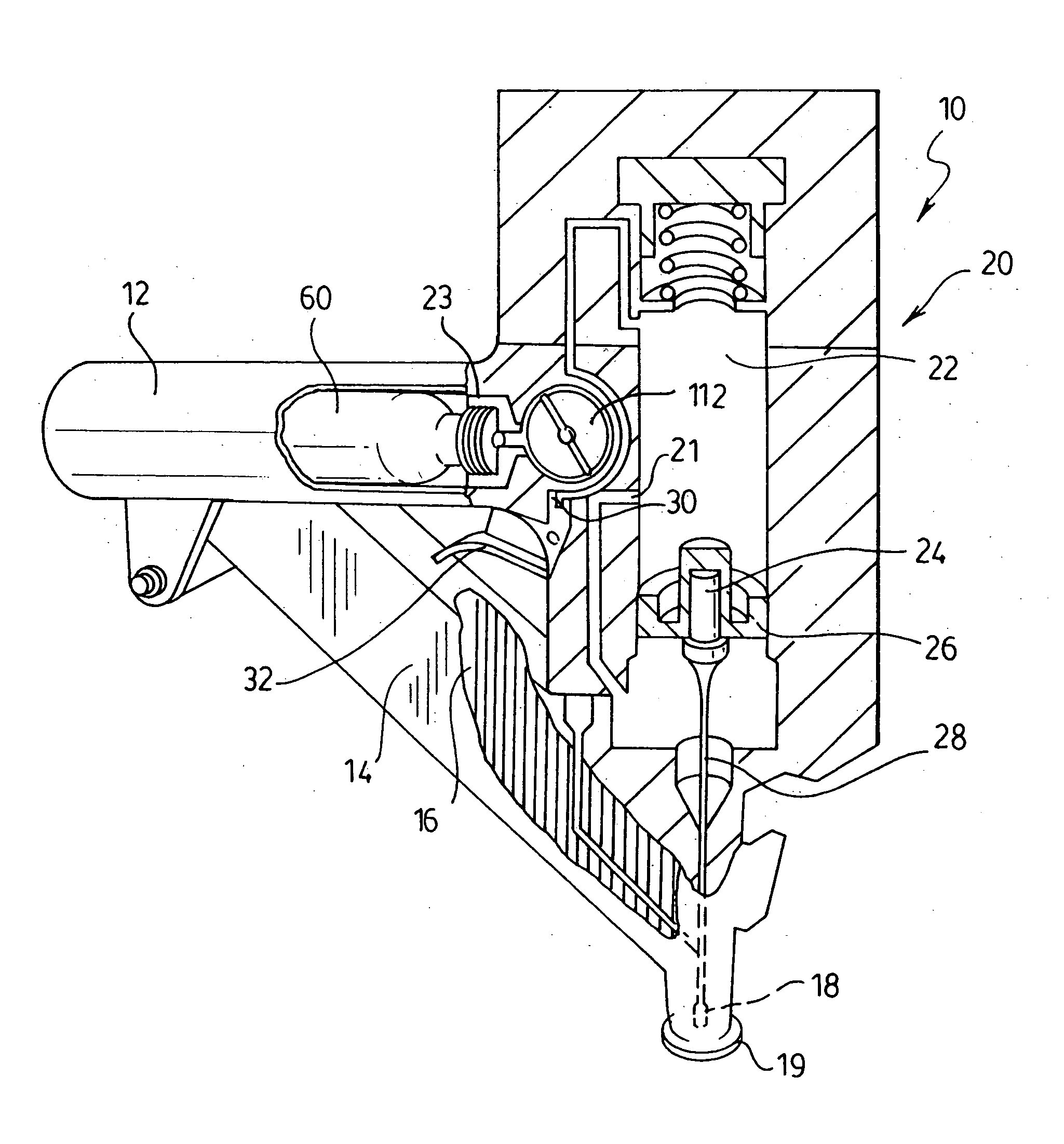
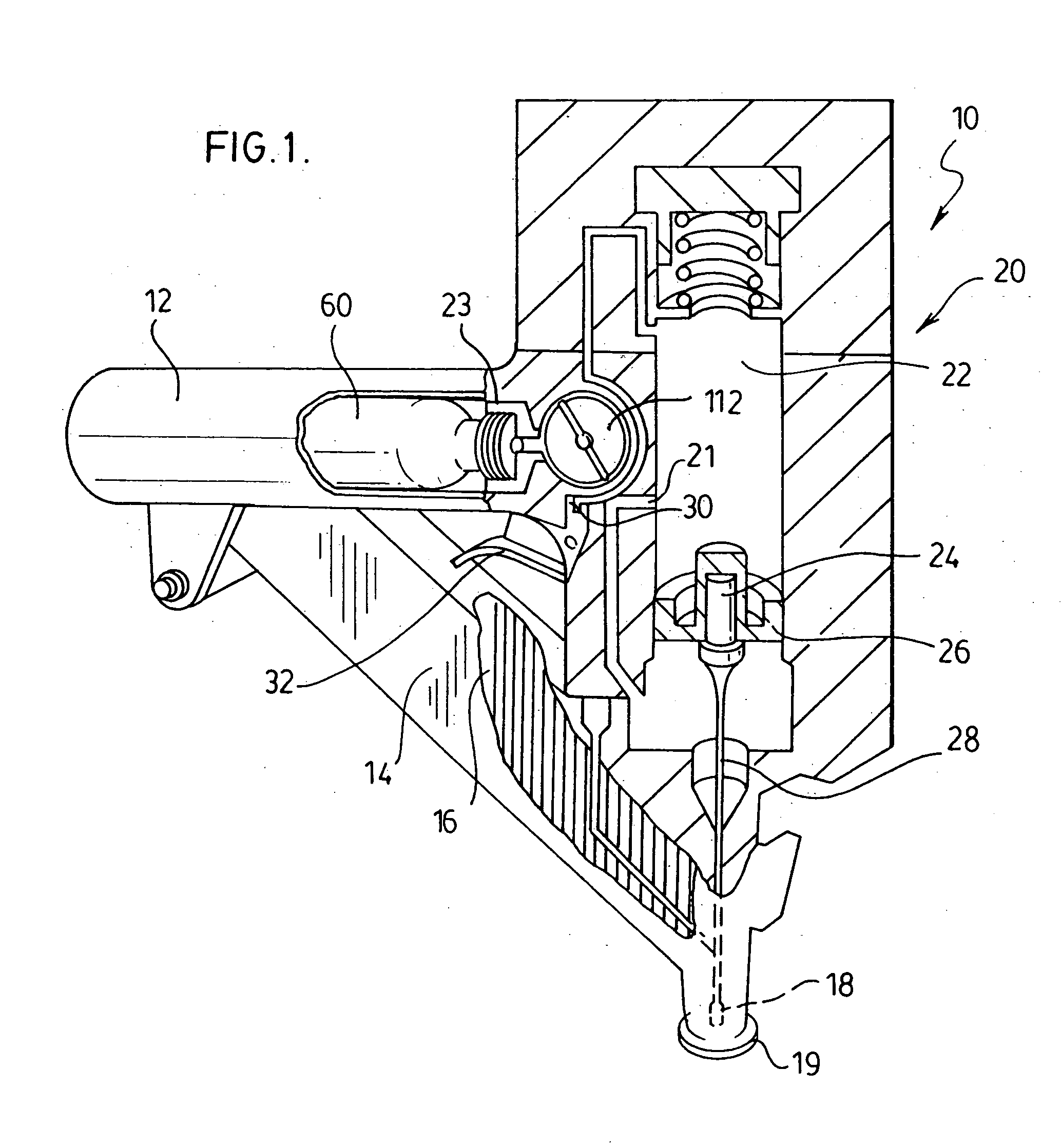
[0023]FIG. 1 illustrates a first preferred embodiment of the invention. A hand-held pneumatic fastener driving tool 10 has a drive head 20 affixed to a fastener magazine 14 having a spring-loaded feeder 16 that feeds nails or brads 2 to a fastener outlet 18. A handle 12 is affixed between the drive head 20 and the magazine 14, creating a stable, unitary construction that maintains the drive head 20 in proper alignment with the magazine 14. The pneumatic cylinder 22 contains a piston 24 mounted in a bearing 26 for axial reciprocation within the cylinder 22 and affixed to a shaft or “dr...


PUM

PropertyMeasurementUnit
Forceaaaaaaaaaa
Sizeaaaaaaaaaa

Abstract

A self-contained pneumatic fastener driving tool that operates from a compressed gas canister supported by a local holder. The gas canister is either connected to the driving tool by a short pneumatic hose, in which case the gas canister is preferably secured to a belt or other device which is mounted on or attached to the user, or in some embodiments affixed to a local holder integrated into the driving tool, mounted alongside the handle of the tool, through the handle of the tool, or mounted directly to the drive head of the tool such that the gas canister itself serves as a handle for the tool. The gas canister provides a source of compressed gas sufficient for hundreds of strokes having the required percussive force, while not suffering from the constraints of attachment to an air compressor. The local canister holder may be expandable, to allow for canisters of different sizes and types to be mounted.

Description

FIELD OF THE INVENTION [0001] This invention relates to pneumatic tools. In particular, this invention relates to a self-contained pneumatic fastener driving system. BACKGROUND OF THE INVENTION [0002] A pneumatic fastener driver, commonly known as a “nail gun” or “air nailer,” is very useful for jobs require the driving of a large number of fasteners or the driving of fasteners in tight places where there is insufficient clearance to swing a hammer. [0003] A typical pneumatic fastener driving tool has a drive head affixed to a fastener magazine having a spring-loaded feeder that feeds nails or brads to a fastener outlet. The drive head contains a pneumatic cylinder containing a piston that has a shaft or “driver blade” aligned with the fastener outlet. The cylinder is in communication with an air compressor, through a valve actuated by a trigger. When the trigger is depressed the cylinder is momentarily pressurized, driving the piston shaft against the fastener head to in turn drive...

Claims


Application Information

Patent Timeline
IPC IPC(8): B25C1/04B25C5/02
CPCB25C1/04
Inventor PATRICK, STEPHEN
Owner D & S PROD SOLUTIONS
Learn More