Semi-trailing arm high cube rear suspension

a rear suspension and semi-trailing arm technology, applied in the field of vehicle suspension, can solve the problems of low ground clearance, unwanted toe change, and conventional independent rear suspensions that do not maximize the available cargo space, so as to improve cargo space, reduce the moment, and improve the effect of braking for

Inactive Publication Date: 2005-11-17
DANA CORP
View PDF21 Cites 15 Cited by
  • Summary
  • Abstract
  • Description
  • Claims
  • Application Information

AI Technical Summary

Benefits of technology

[0010] A suspension in accordance with the present invention is advantageous as compared to existing independent rear suspensions. In particular, the location of the outboard pivot attachment relative to the wheel enables a better reaction to braking force. Specifically, this configuration serves to reduce moment in the fore / aft direction about the pivot attachments to avoid a toe change in the wheel. Various embodiments of the inventive suspension may also improve cargo space, reduce the chance of damage during a tire blowout or flat and control camber change to improve handling.

Problems solved by technology

First, conventional independent rear suspensions create a large load on the pivot attachments during braking due to the fore / aft moment and may create an unwanted toe change in which the front of the wheel is angled in toward the vehicle or out away from the vehicle.
Second, conventional independent rear suspensions do not maximize the available cargo space or may suffer from low ground clearance.
Third, conventional independent rear suspensions may have adverse wheel camber.

Method used


Image

  • Semi-trailing arm high cube rear suspension
  • Semi-trailing arm high cube rear suspension
  • Semi-trailing arm high cube rear suspension

Examples


Embodiment Construction

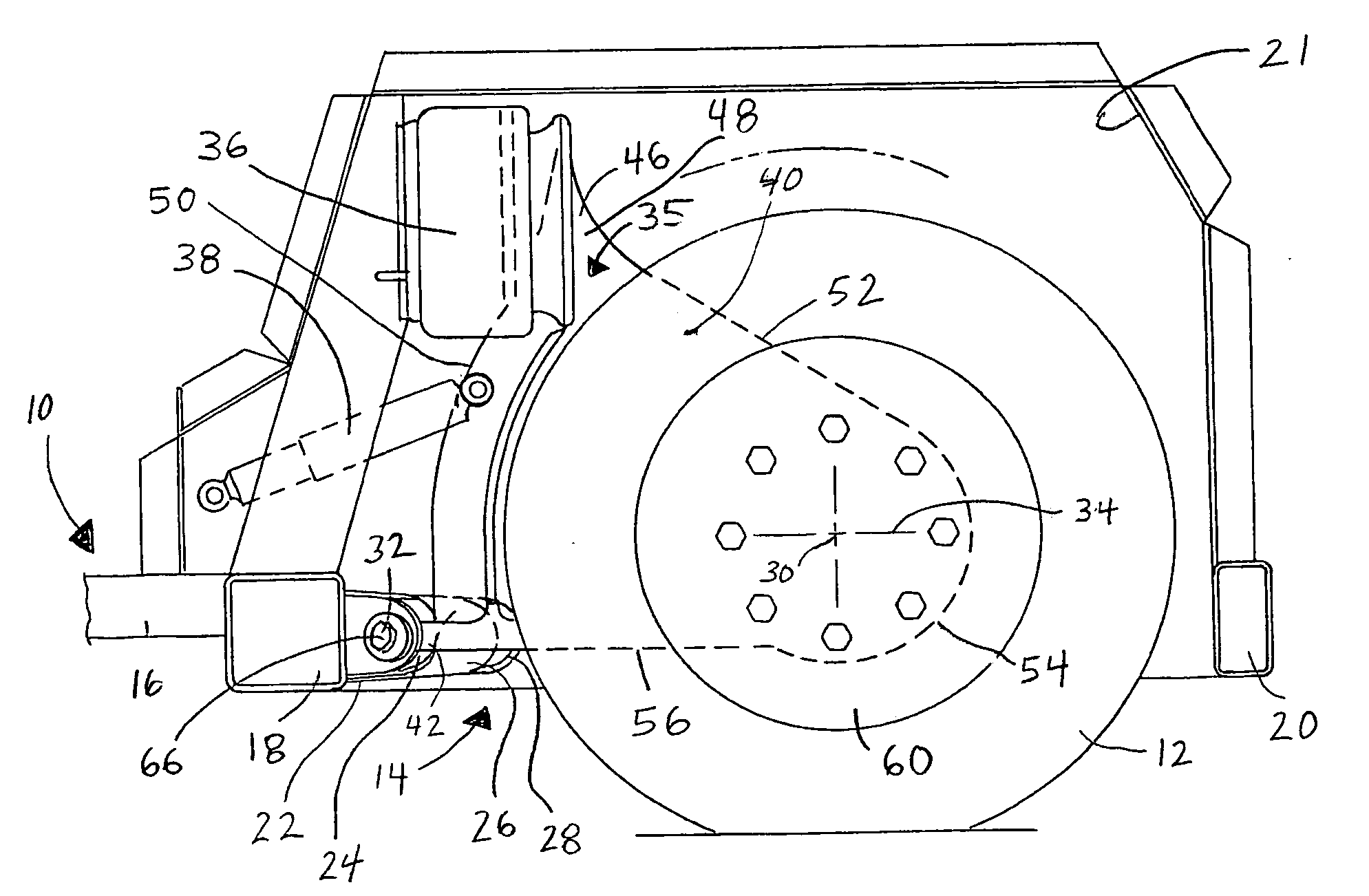
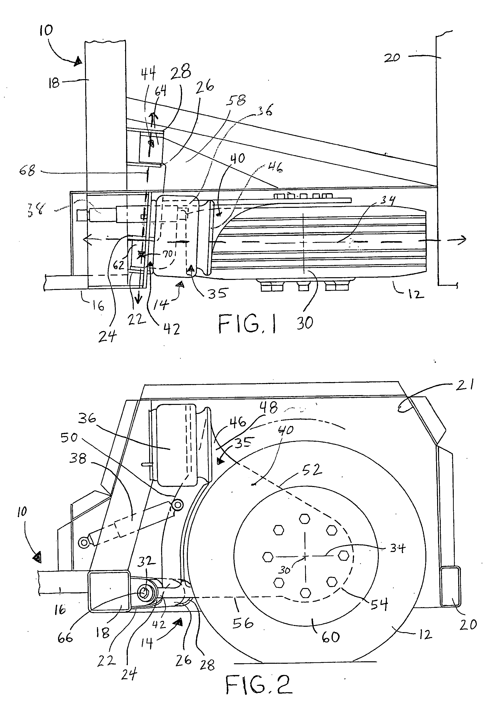
[0017] Referring now to the drawings wherein like reference numerals are used to identify identical components in the various views, FIG. 1 illustrates a portion of a vehicle frame 10 supported on one or more wheels 12 through a vehicle suspension 14 in accordance with one embodiment of the present invention. The inventive suspensions disclosed herein are designed for use in low floor vehicle including those designed to transport people (i.e., buses) and / or cargo. It should be understood, however, that the inventive suspension could be used on other vehicle types.

[0018] Frame 10 is provided to support various components of the vehicle and is conventional in the art. Frame 10 may include includes conventional rail members 16 extending in the longitudinal direction of the vehicle generally parallel to one another and one or more cross members 18, 20 extending transversely relative to the rail members. Frame 10 may further include additional structure supported on members 16, 18, 20 a...


PUM


Abstract

An improved semi-trailing arm rear suspension is provided for use in vehicles having low floors. The suspension positions the outboard pivot attachment further outboard than the longitudinal centerline of the wheel to improve reaction during vehicle braking. The suspension may also place the pivot axis below the rotational axis of the wheel in order to maximize available cargo space and at a slight angle to the rotation axis of the wheel to improve vehicle handling.

Description

BACKGROUND OF THE INVENTION [0001] 1. Field of the Invention [0002] The present invention relates to a vehicle suspension, and more particularly, to independent rear suspension for a low floor vehicle. [0003] 2. Discussion of Related Art [0004] A conventional independent rear suspension is used to support the wheels of a vehicle in which a wide and low cargo floor is desired. In particular, the suspension can be used in connection with non-driving wheels, for example, with a trailer or with the rear wheels of a front wheel drive vehicle. In an independent rear suspension, the two rear wheels are sprung independently from each other. The advantages of an independent rear suspension over a beam axle suspension, in which an axle extends the width of the vehicle below the vehicle frame, is that a larger trunk or cargo area can be placed between the wheels. Moreover, handling over rough road surfaces can be improved using an independent rear suspension. [0005] One type of conventional in...

Claims


Application Information

Patent Timeline
Patent Type & Authority Applications(United States)
IPC IPC(8): B60G3/12B60G3/14B60G7/00B60G7/02B60G11/27
CPCB60G3/14B60G7/00B60G11/27B60G2200/132B60G2202/152B60G2204/126B60G2300/38B60G2204/13B60G2204/143B60G2206/11B60G2300/042B60G2300/14B60G2204/129
Inventor ZIECH, JAMES F.
Owner DANA CORP
Why Eureka
Try Eureka