
Biometrically authenticated portable access device

a portable access device and biometric authentication technology, applied in the direction of program control, testing/monitoring control system, instruments, etc., can solve the problems of non-control, unauthorized users being presented to access the protected resource, and not allowing third parties to program the rfid tags used with their rfid system

Inactive Publication Date: 2005-11-17
ASSA ABLOY AB
View PDF24 Cites 111 Cited by
  • Summary
  • Abstract
  • Description
  • Claims
  • Application Information

AI Technical Summary

Benefits of technology

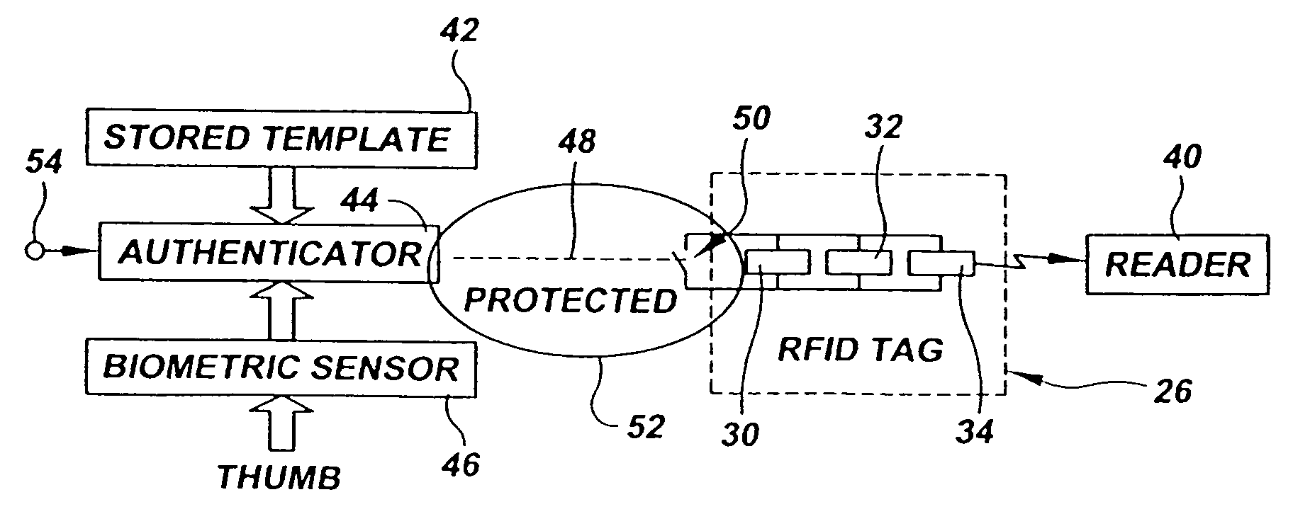
[0018] An electronic switch is connected to the authenticator and enables an RFID tag when the authorization signal from the authenticator indicates that the live biometric parameter matches the stored biometric template. The RFID tag is a conventional RFID tag programmable in a conventional RFID tag programmer selected from an installed base of RFID programmers used for programming RFID tags that do not include associated biometric sensors. The use of a conventional RFID tag allows the portable RFID access device to be programmed by and used with existing installed systems of proprietary and non-proprietary readers and programmers.

Problems solved by technology

If the authorized RFID tag is lost or stolen, however, it can be presented by an unauthorized user to access the protected resource.
In general these companies do not allow third parties to program the RFID tags used with their RFID system except in the case of using certain leased card programmers which are provided to trusted distributors for use with RFID tags that they provide to their customers.
There is also a non-proprietary, non-controlled format available, which is known as “26 bit wiegand.” This format is not recommended for high security applications and is not appropriate for use where biometric verification is used as a secondary layer of security.
The proprietary nature of the coding and signaling of existing installed systems, the restrictions on programming, as well as technical considerations make it difficult to simulate the operation of existing proprietary RFID tags with an RFID engine constructed from generic logic elements.
Owners of proprietary RFID systems are often unwilling to disclose details of the proprietary system that are needed for simulation in an RFID engine.
Moreover, even where such information is available, the programming procedure for an RFID engine simulating an RFID tag may be incompatible with the installed base of programmers used with the proprietary system.

Method used


Image

  • Biometrically authenticated portable access device
  • Biometrically authenticated portable access device

Examples


Embodiment Construction

)

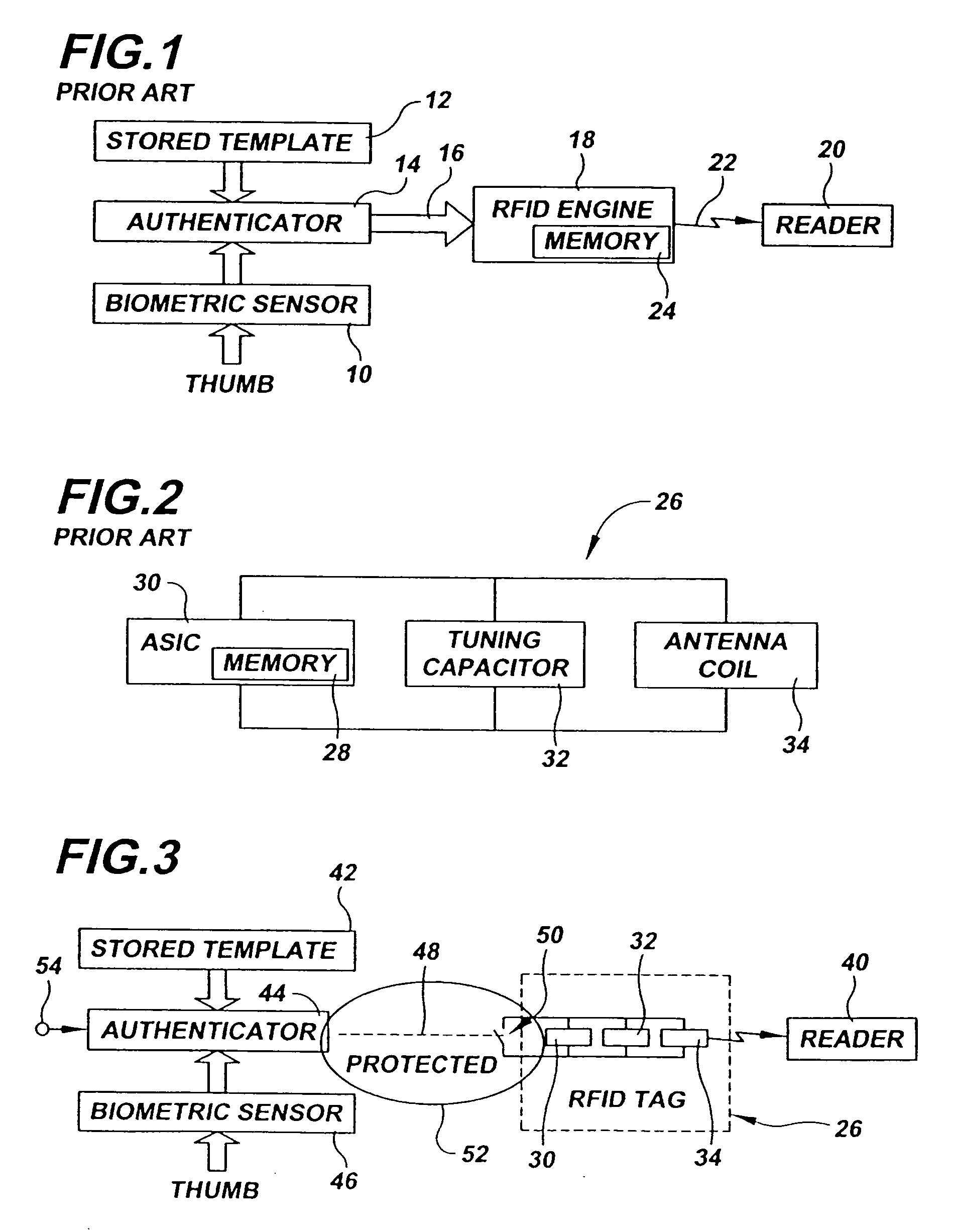
[0027] In describing the preferred embodiment of the present invention, reference will be made herein to FIGS. 1-3 of the drawings in which like numerals refer to like features of the invention.

[0028] A block diagram of a typical prior art biometric key fob is shown in FIG. 1. An authorized user verifies his identity to the key fob using a biometric sensor 10. The biometric sensor is typically a semiconductor device capable of detecting the location of ridges forming a user's fingerprint as the ridges contact the sensor. In a conventional design, the user's thumb is applied to the biometric sensor, which produces a live authentication signature corresponding to the user's thumbprint.

[0029] A previously established authentication signature corresponding to the authorized user's thumbprint is located in stored biometric template 12. The authenticator 14 compares the live biometric parameter measured by the biometric sensor 10 to the stored biometric template 12 for the authorized u...


PUM


Abstract

A biometrically authenticated portable access device, includes a biometric sensor for measuring a live biometric parameter of an unverified user, an authenticator controlling a switch that enables and disables a conventional RFID tag and a stored biometric template corresponding to a previously measured biometric parameter of an authorized user. The authenticator compares the live biometric parameter of the unverified user to the stored biometric template and enables the RFID tag when the live biometric parameter matches the stored biometric template. The RFID tag is programmable in conventional RFID tag programmers that may be proprietary permitting the portable access device to be used with existing installed systems of proprietary and non-proprietary RFID tag programmers and readers.

Description

BACKGROUND OF THE INVENTION [0001] 1. Field of the Invention [0002] The present invention relates to biometrically authenticated access control in which a wireless authorization signal is sent from a portable unit, such as a key fob, after a biometric sensor on the portable unit has verified the identity of the user. [0003] More specifically, the present invention relates to radio frequency identification (RFID) technology used in such devices. [0004] 2. Description of Related Art [0005] Radio Frequency Identification (RFID) systems use an RFID reader to wirelessly detect the presence of a nearby RFID tag and read an identification code stored in the tag. The identification code in the RFID tag can be used to control access to a protected resource by allowing access only when an RFID tag having an authorized identification code is detected. Generally, the authorized RFID tag is issued to an authorized user to ensure that only the authorized user has access to the protected resource....

Claims


Application Information

Patent Timeline
IPC IPC(8): G05B19/00G06F21/00G06K19/07G06K19/073G07C9/00H04Q1/00
CPCG06F21/32G06K19/0723G07C2009/00095G07C9/00087G06K19/07354G07C9/26G07C9/257G06K17/00G06K19/07G06F18/00
Inventor LOWE, PETER R.
Owner ASSA ABLOY AB
Learn More