Deformable mirror holders

a mirror and holder technology, applied in the field of mirror holders, can solve the problems of affecting the optical properties of the mirror, and causing the inflexion area to have undesirable optical properties,

Inactive Publication Date: 2005-11-17
BAE SYSTEMS PLC
View PDF10 Cites 34 Cited by
  • Summary
  • Abstract
  • Description
  • Claims
  • Application Information

AI Technical Summary

Benefits of technology

[0012] The present invention aims to overcome or at least substantially reduce some of the above mentioned drawbacks associated with known mirror / mirror holder designs.

Problems solved by technology

However, conventional designs mean that there is a reciprocal relationship between these two parameters, and one parameter can only be improved at the expense of the other.
However, it has an inherent disadvantage in that it creates a dead space around the mirror's edge.
The annular area between the active area and the annular ring must bend in the opposite sense and so forms an area of inflexion that has undesirable optical properties.
However, this arrangement is to the detriment of ruggedness and the twisting introduces unwanted distortions leading to an optically inferior performance.
For the larger mirrors this will adversely affect the minimum curvature available from the mirror.
However, the overriding issue with this type of deformable mirror is the cost.
Although there are a number of different actuator technologies available, none of them are cheap.
This makes large mirrors expensive because as many as 300 actuators may be required.
For a bonded piezoelectric element mirror, although a large piezoelectric element will be more expensive than a smaller one, the cost differential will not be as great.
A second issue is that it is not always possible to place discrete actuators as close to each other as required because of their fairly large size.

Method used


Image

  • Deformable mirror holders
  • Deformable mirror holders
  • Deformable mirror holders

Examples


first embodiment

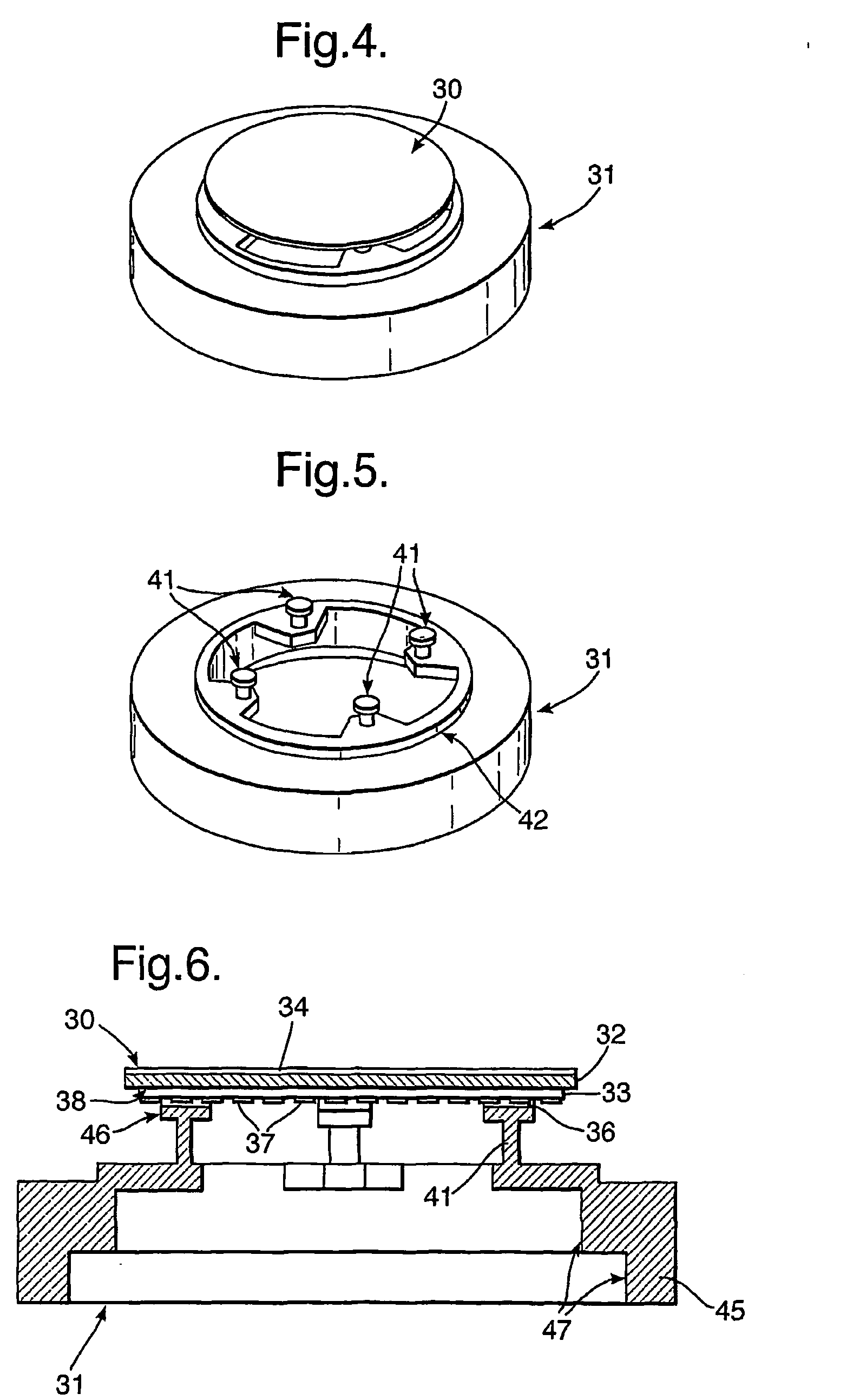
[0060] A deformable bimorph mirror 30 and a mount 31 according to the present invention are shown in FIG. 4. The mount 31 is a unitary structure made from stainless steel material. The mount 31 comprises a round body that defines a receiving portion (as partially shown) sized and shaped to receive and support the disc-shaped deformable bimorph mirror 30 on top. As is shown in the Figure, the mirror 30 in its assembled (upright) condition on top of the mount 31 is held clear of the mount 31.

[0061]FIG. 5 shows the mirror mount 31 of FIG. 4, without the mirror 30 for sake of clarity. The mount has a stepped profile 42 defining a generally circular aperture in the centre. Four flexure supports 41 are formed in equispaced relationship around the top most stepped section 42 of the mount body, each support being arranged to extend inwardly towards the centre of the aperture before turning upwards through 90° to extend in an upward direction for supporting the mirror (not shown). The four f...

fifth embodiment

[0082]FIG. 12 shows the present invention, without the mirror mount base for clarity (i.e. as viewed from the mirror's reverse side). In this embodiment, almost the entire inner face of the mirror substrate 32 is supported by a generally solid compliant material 60. This arrangement broadly corresponds to an inversion of the FIG. 11 arrangement in that whilst there are seventeen hole formations 61 in the compliant material 60 to permit connection to each of the mirror electrodes, most of the backside of the mirror is effectively supported by the compliant material 60.

[0083] In this embodiment, the compliant material of the passive support structure is rubber, epoxy or some form of metal (or other type foam). If desired, the compliant material could be readily configured as a narrow ridge structure (i.e. similar to the type of ridges that are used to stiffen up light structures) that follows the gaps between the mirror electrodes.

[0084]FIG. 13 shows an exploded cross-sectional view ...


PUM


Abstract

This invention concerns improvements relating to a deformable-mirror holder for holding a mirror in a desired position, to within accepted tolerances, even whilst the mirror is deforming or in a deformed state. More particularly but not exclusively, this invention relates to a holder for a bimorph mirror. A deformable mirror holder (31) is provided comprising a body with a receiving portion for receiving a deformable mirror (30), and wherein the receiving portion is defined by a passive flexible support structure (41) such that, in use, to the support structure provides a supporting surface to the mirror. This invention extends to a deformable mirror and a deformable mirror holder as described above.

Description

FIELD OF THE INVENTION [0001] This invention concerns improvements relating to a deformable mirror holder for holding a mirror in a desired position, to within accepted tolerances, even whilst the mirror is deforming or in a deformed state. More particularly but not exclusively, this invention relates to a holder for a bimorph mirror. BACKGROUND OF THE INVENTION [0002] Deformable mirrors are often used in the field of adaptive optics. For example, phase distortions in a signal may be sensed by a wavefront sensor and these distortions may be corrected for by an adaptive mirror. Such adaptive mirrors may be employed in numerous fields, including: [0003] imaging, for example adaptive mirrors are used in astronomy to improve the resolution of earth-based telescopes that are otherwise affected by atmospheric distortions; [0004] laser sensing, where the amount of laser light that can be delivered onto a target is significantly increased by using an adaptive mirror to correct for atmospher...

Claims


Application Information

Patent Timeline
Patent Type & Authority Applications(United States)
IPC IPC(8): G02B7/185G02B7/188G02B26/08
CPCG02B26/0858G02B26/0825
Inventor GRIFFITH, MICHAEL STEWARTLAYCOCK, LESLIE CHARLESARCHER, NICHOLAS JOHNMCCARTHY, ANDREW GRAHAM
Owner BAE SYSTEMS PLC
Why Eureka
Try Eureka