Electroacoustic transducer

a transducer and electroacoustic technology, applied in the direction of electrical transducers, transducer details, printed circuits, etc., can solve the problems of abnormal vibration in the diaphragm, coil terminal breakage, stress concentration in a part of the coil terminal, etc., to achieve the effect of effectively preventing stress concentration, reducing the mass of the intermediate portion, and well enhancing the flexibility of the intermediate portion

Inactive Publication Date: 2005-11-17
STAR MICRONICS
View PDF2 Cites 24 Cited by
  • Summary
  • Abstract
  • Description
  • Claims
  • Application Information

AI Technical Summary

Benefits of technology

[0023] In the above configuration, in the flexible printed circuit board, widths of portions where the intermediate portion is connected to the end portions may be gradually increased as advancing from the intermediate portion to the end portions. According to the configuration, the stress distributions in the connecting portions can be uniformed. Therefore, it is possible to more effectively prevent stress concentration from occurring in the flexible printed circuit board.
[0024] In the above configuration, when the width of the intermediate portion of the flexible printed circuit board is set to be equal to or smaller than 2 mm, the flexibility of the intermediate portion can be well enhanced, and the mass of the intermediate portion can be sufficiently reduced. According to the configuration, the energy of characteristic vibration of the flexible printed circuit board can be sufficiently reduced. In this case, more preferably, the width of the intermediate portion is set to be equal to or smaller than 1.5 mm, and further preferably equal to or smaller than 1 mm.
[0025] In the above configuration, the specific value of the thickness of the flexible printed circuit board is not particularly limited. When the thickness is set to be a value which is equal to or smaller than 0.25 mm, the flexibility of the intermediate portion can be well enhanced, and the mass of the intermediate portion can be sufficiently reduced. According to the configuration, the energy of characteristic vibration of the flexible printed circuit board can be sufficiently reduced. In this case, more preferably, the thickness of the intermediate portion is set to be equal to or smaller than 0.15 mm, and further preferably equal to or smaller than 0.1 mm.
[0026] In the above configuration, when electrical conduction and fixation between the conductive patterns and the coil terminals are conducted by thermocompression bonding, the workability of the electrical conduction and fixation can be enhanced as compared with the case where the electrical conduction and fixation are conducted by soldering or the like. When the electrical conduction and fixation on the movable side are conducted by thermocompression bonding as described above, performance degradation caused by, for example, deformation of the flexible printed circuit board due to heat generated in soldering, and characteristic reduction of the electroacoustic transducer due to variation of the amount of supplied solder can be prevented from occurring.
[0027] In the above configuration, when the end portion of the flexible printed circuit board on the side of the coil terminals is clampingly held by the voice coil and the diaphragm, a large load can be prevented from being accidentally applied to portions of the coil terminals which are electrically conductively fixed to the conductive patterns. According to the configuration, it is possible to more effectively prevent conductor breakage from occurring in the coil terminals and the like.
[0028] In the above configuration, the upper end portion of the voice coil may be supported by a predetermined coil supporting member, and an engagement structure for engagingly holding the end portion of the flexible printed circuit board on the side of the coil terminals may be disposed on the coil supporting member. In this configuration, electrical conduction and fixation between the conductive patterns and the coil terminals can be conducted in a state where the flexible printed circuit board is positioned. As a result, the workability of the electrical conduction and fixation can be further enhanced.

Problems solved by technology

When the transducer is used at a high sound pressure, therefore, there arises a problem in that stress concentration occurs in a part of the coil terminals and the coil terminals are likely to be broken.
Consequently, there is a problem in that characteristic vibration of the flexible printed circuit board is transmitted to the diaphragm and abnormal vibration is likely to occur in the diaphragm.
In this case, however, there is another problem in that stress concentration occurs in the vicinity of the both ends of the flexible printed circuit board, and conductor breakage is likely to occur in the flexible printed circuit board.

Method used


Image

  • Electroacoustic transducer
  • Electroacoustic transducer
  • Electroacoustic transducer

Examples


Embodiment Construction

[0034] Hereinafter, an embodiment of the invention will be described with reference to the accompanying drawings.

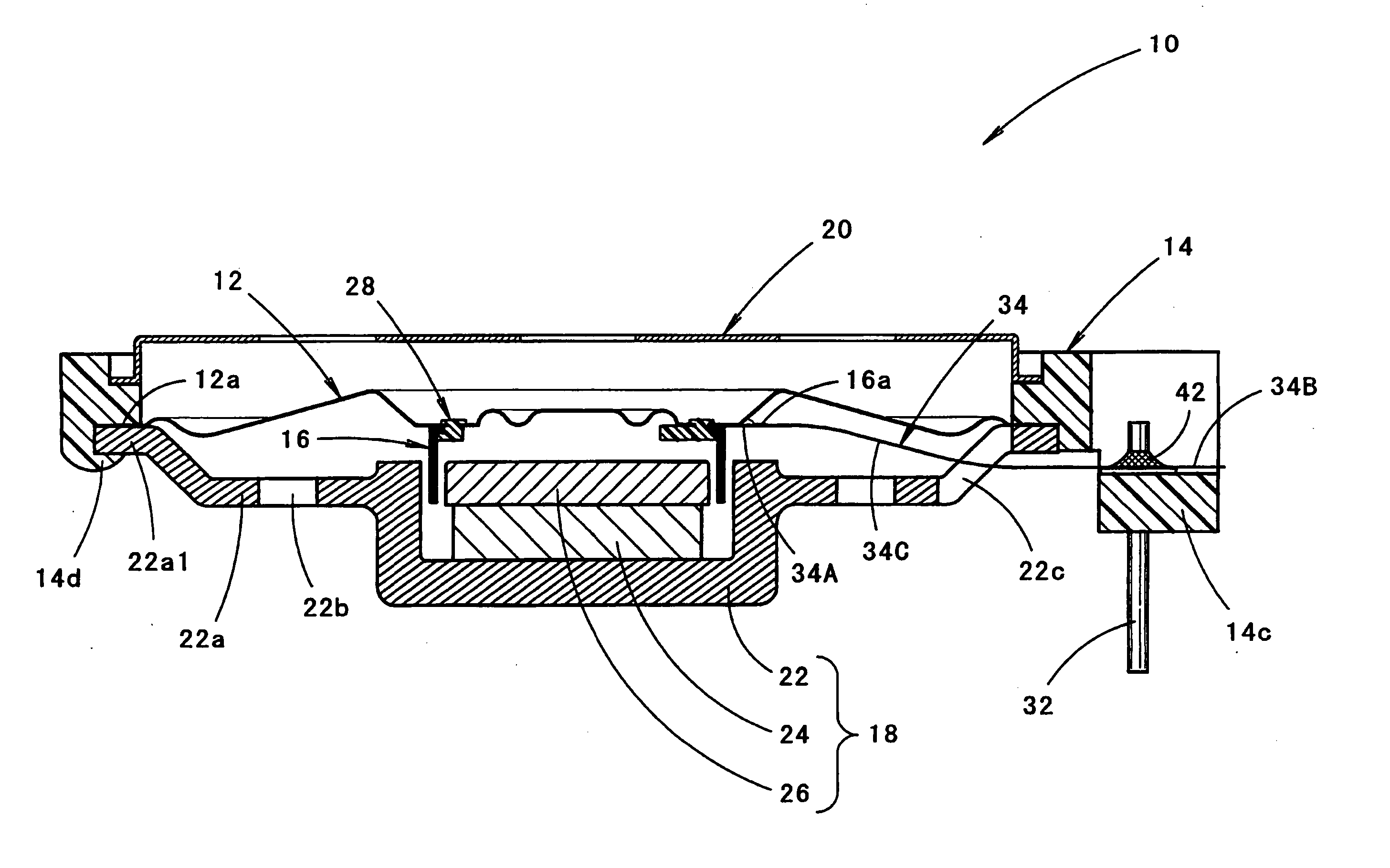
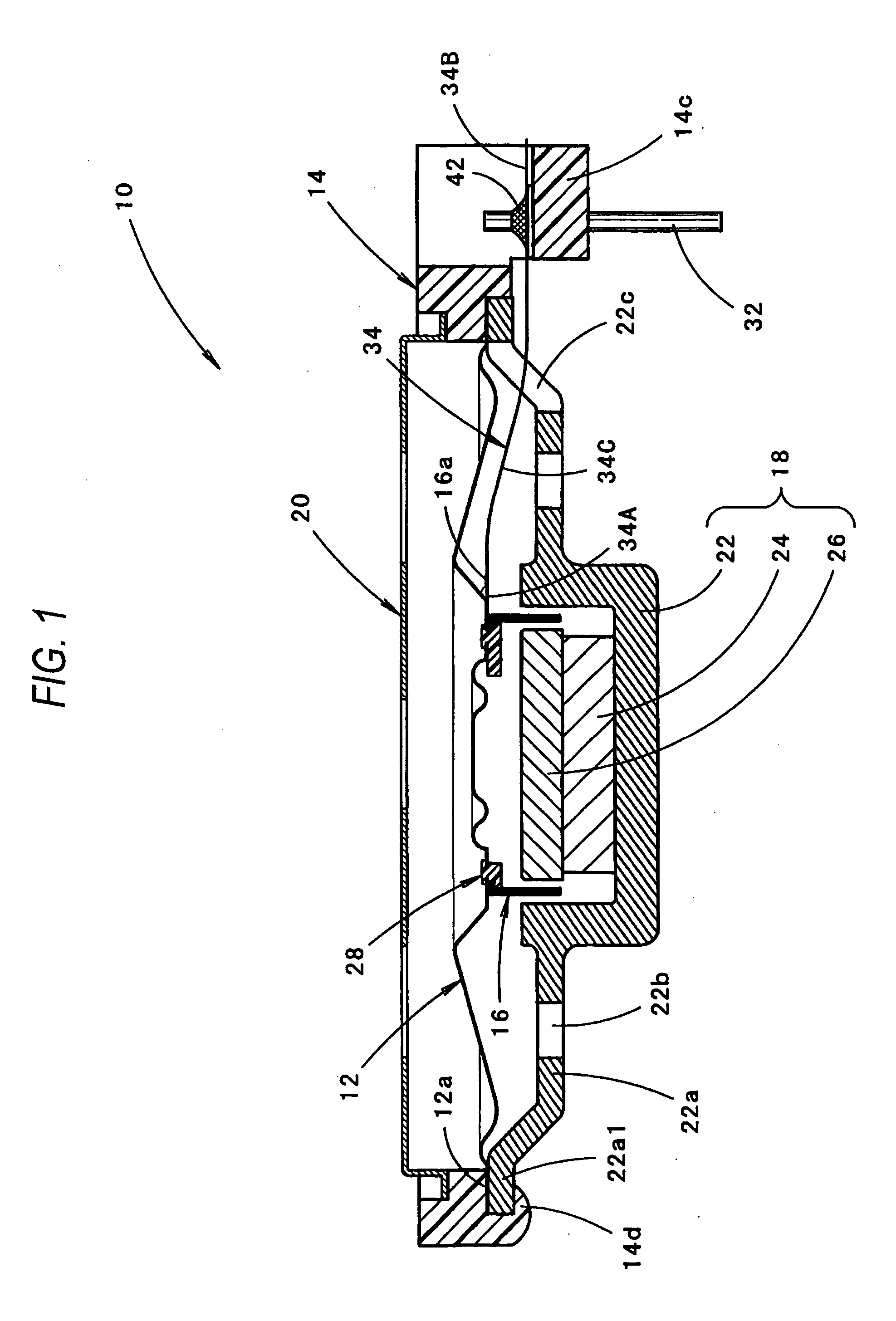
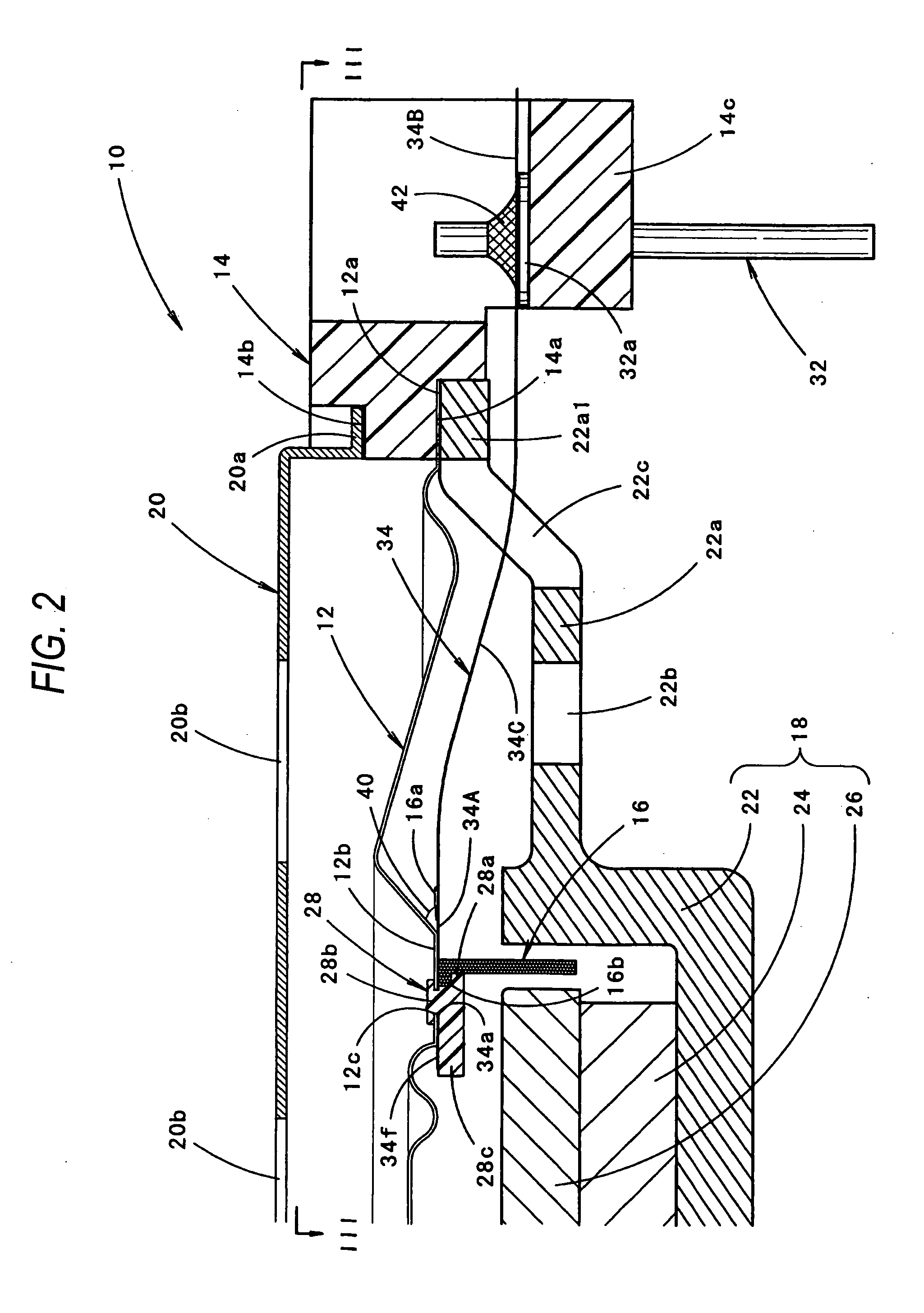
[0035]FIG. 1 is a side sectional view of an electroacoustic transducer 10 of an embodiment of the invention in a state where the transducer is upward directed, FIG. 2 is a detailed view of main portions of FIG. 1, and FIG. 3 is a view looking in the direction of the line III-III in FIG. 2.

[0036] As shown in the figures, the electroacoustic transducer 10 is a small speaker of the electrodynamic type having an outer diameter of about 10 to 40 mm (for example, about 30 mm), and includes: a diaphragm 12; a frame 14 which supports the diaphragm 12; a voice coil 16 in which an upper end portion is fixed to the lower face of the diaphragm 12; a magnetic circuit unit 18 in which a cylindrical magnetic gap for housing a lower end portion of the voice coil 16 is formed; a cover 20 which covers the diaphragm 12 from the upper side; a pair of terminal members 32 which are attached ...


PUM


Abstract

In an electroacoustic transducer, a pair of coil terminals elongating from a voice coil are electrically connected to a pair of terminal members attached to a frame via a flexible printed circuit board, respectively. According to the configuration, even in a case where an electroacoustic transducer is used at a high sound pressure, breakage of the coil terminals hardly occurs. In the flexible printed circuit board, the width of an intermediate portion is set to be smaller than the widths of an end portion on the side of the coil terminals and an end portion on the side of the terminal members. Therefore, the flexibility of the intermediate portion can be enhanced, whereby transmission of characteristic vibration of the flexible printed circuit board to a diaphragm, and stress concentration in the vicinity of the end portions are effectively suppressed.

Description

BACKGROUND OF THE INVENTION [0001] 1. Field of the Invention [0002] The present invention relates to an electroacoustic transducer of a so-called electrodynamic type. [0003] 2. Description of the Related Art [0004] Generally, an electroacoustic transducer such as an electrodynamic speaker is configured so that a voice coil is fixed to a lower face of a diaphragm, an outer peripheral edge portion of the diaphragm is supported by a frame, and a pair of coil terminals elongating from the voice coil are electrically connected to a pair of terminal members attached to the frame, respectively. [0005] In a small electroacoustic transducer having such a configuration, as disclosed in, for example, JP-A-2001-292493, the coil terminals are often led as they are to be located on the frame, and then electrically conductively fixed directly to the terminal members. [0006] By contrast, JP-UM-A-1-82597 discloses an electroacoustic transducer in which terminal members and coil terminals are electri...

Claims


Application Information

Patent Timeline
Patent Type & Authority Applications(United States)
IPC IPC(8): H04R1/06H04R9/04H04R25/00H05K1/00
CPCH05K1/0393H04R1/06
Inventor KITAMURA, HAJIMEIMAHORI, YOSHIOFUSHIMI, ISAO
Owner STAR MICRONICS
Why Eureka
Try Eureka