
Superconducting filter device

a filter device and superconducting technology, applied in superconductors/hyperconductors, waveguides, conductive materials, etc., to achieve the effect of eliminating the loss of signal due to the adjust plate and widening the bandwidth

Active Publication Date: 2005-11-17
FUJITSU LTD
View PDF7 Cites 5 Cited by
  • Summary
  • Abstract
  • Description
  • Claims
  • Application Information

AI Technical Summary

Benefits of technology

[0012] A more specific object of the present invention is to provide a compact superconducting filter device which can easily change a bandwidth and a center frequency without changing a pattern or shape of the filter.
[0021] According to the present invention, there are two resonance frequencies generated in the filter pattern by locating the adjust plate above the filter pattern. By changing and adjusting the distance between the adjust plate and the filter pattern, the resonance frequency on the lower frequency side and the higher frequency side can be changed, which enables the bandwidth being wider or narrower. Additionally, a signal loss due to the adjust plate can be eliminated by forming the adjust plate by a superconductor material.

Problems solved by technology

Problems lie in putting such a superconducting filter in practical use, such as, for example, a problem in producing a low-temperature environment, have been greatly eliminated.

Method used


Image

  • Superconducting filter device
  • Superconducting filter device
  • Superconducting filter device

Examples


Embodiment Construction

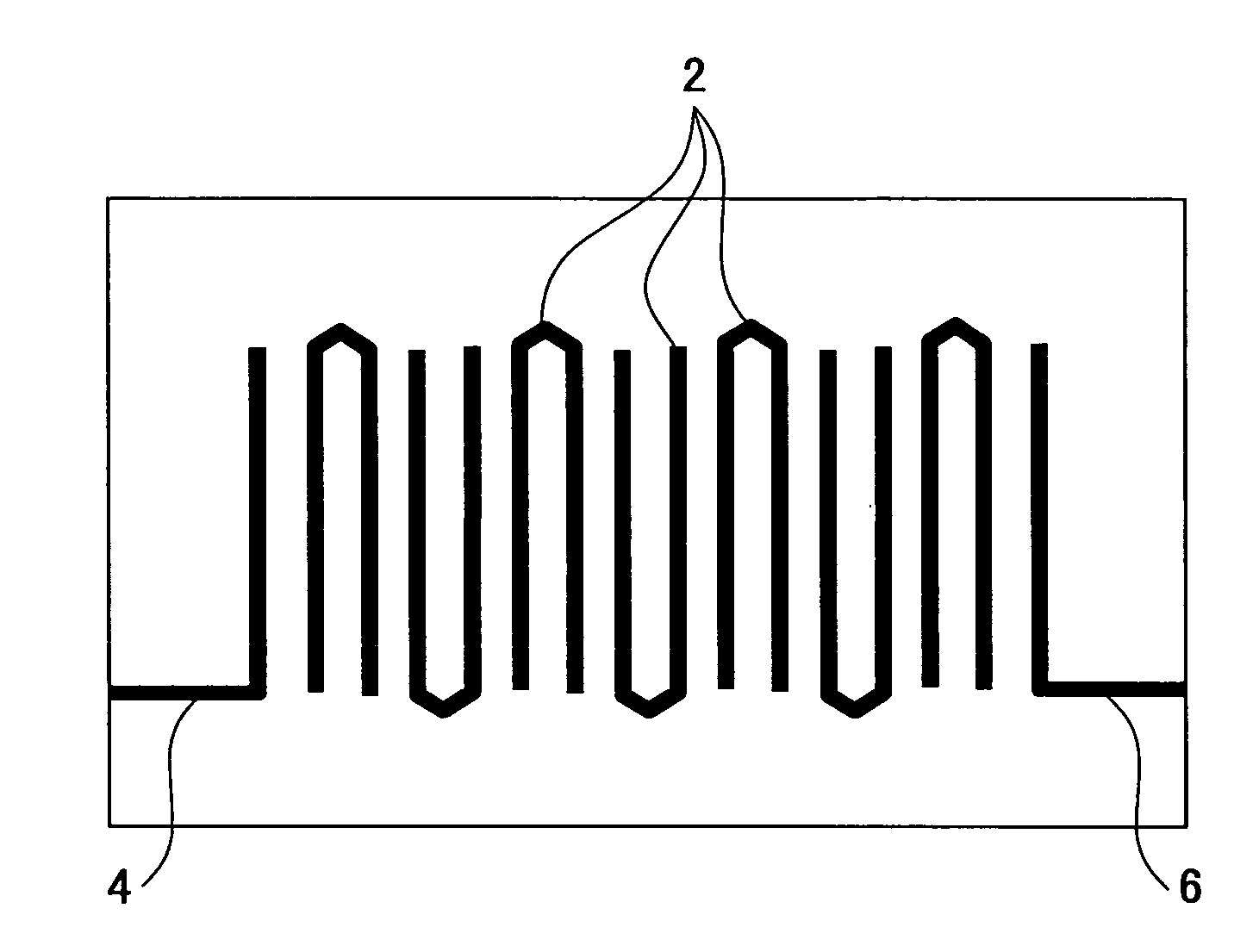
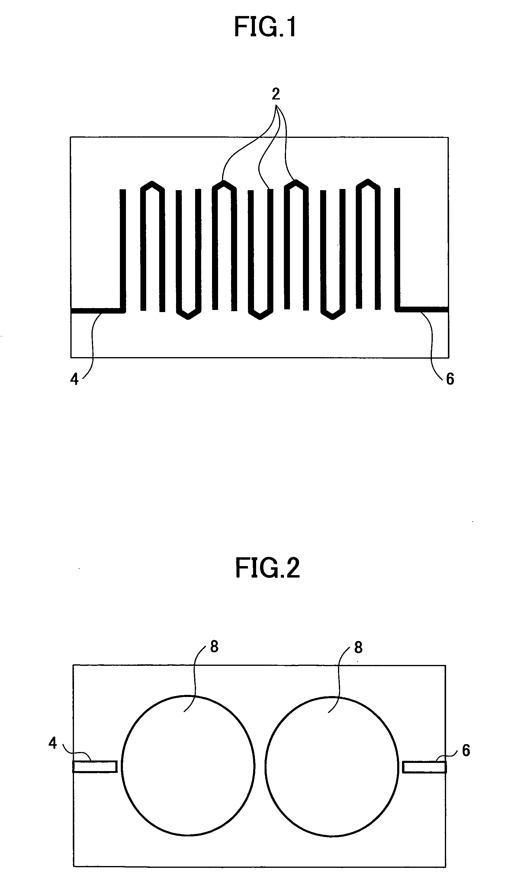
[0034] Many superconducting filters for reception are constituted as a filter in which a plurality of hairpin type resonators are arranged between a signal input line 4 and a signal output line 6 as shown in FIG. 1. If the superconducting filter for reception of such a structure is used for a circuit for transmission, there may be a problem in that a superconducting state cannot be maintained depending on a condition of use. That is, the circuit for transmission is provided with a larger power than the circuit for reception and a current may be concentrated into a part of the filter constituted by the plurality of hairpin type resonators when a large power is applied thereto, which may result in an increase in the temperature of the semiconductor. Due to such an increase in the temperature, the temperature of the semiconductor may exceed a critical temperature, and, thus, it may be difficult to maintain the superconducting state.

[0035] Thus, in order to improve withstand electric p...


PUM


Abstract

A compact superconducting filter device can easily change a bandwidth and a center frequency without changing a pattern or shape of the filter. A filter pattern is formed on a substrate made of a dielectric material. The filter pattern is made of a superconductor material. A signal input line and a signal output line are formed on the substrate so as to extend from a periphery of the filter pattern. An adjust plate is located above the filter pattern with a predetermined distance therebetween. The adjust plate is formed of one of an electrically conductive material, a superconductive material and a dielectric material.

Description

CROSS-REFERENCE TO THE RELATED APPLICATIONS [0001] This is a continuation-in-part application of application Ser. No. 10 / 947,541 filed Sep. 23, 2004.BACKGROUND OF THE INVENTION [0002] 1. Field of the Invention [0003] The present invention generally relates to superconducting filter devices and, more particularly, to a superconducting filter device used for a receiver amplifier provided in a base station of a portable telephone communication system. [0004] 2. Description of the Related Art [0005] In recent years, with the explosive development and popularization of portable telephones, there is a demand for development of a signal transmission technique that enables a high-speed, large-capacity signal transmission. As a technique which satisfies such as demand, there is suggested a technique using a superconducting filter as a frequency band filter used for a receiver amplifier provided in a base station of a portable telephone communication system. [0006] A superconducting material ...

Claims


Application Information

Patent Timeline
IPC IPC(8): H01B1/00H01P1/203H01L39/00H01P1/208H01P7/08
CPCH01P1/20381Y10S505/866Y10S505/70
Inventor NAKANISHI, TERUAKASEGAWA, AKIHIKOKAI, MANABUYAMANAKA, KAZUNORI
Owner FUJITSU LTD
Learn More