Clamping assembly

Inactive Publication Date: 2005-11-24
RAPIDJOINT
View PDF2 Cites 4 Cited by
  • Summary
  • Abstract
  • Description
  • Claims
  • Application Information

AI Technical Summary

Benefits of technology

[0031] Advantageously, the gear ratio between the first gear member and the second gear member may be a reduction ratio. This provides the particular benefit that the clamp assembly may accordingly be operated to apply a clamping force by application of a reduced torque to the first gear member which provides ease of operation especially when the torque is to be applied manually, such as with

Problems solved by technology

A particular problem is encountered when trying to clamp together two flat surfaces, end to end.
It would be impractical to use a standard clamp, of the type which seeks to compress items positioned between its jaws.
For instance in FIG. 1, it would be impractical to position a standard clamp around the end points A′ and B′, since, in practice, objects A and B are likely to be very long.
Moreover, if a standard clamp were to be placed over the end points A′ B′, a likely result when the clamping portions are brought together is that objects A and B may be forced out of linear alignment.
The problem remains, however, that it is very difficult to manipulate known clamps in cut-away portions such as the one designated as A″, B″, C″ in FIG. 2.
A reason for the difficulty is that, in use, this form of clamping needs to be implemented sometimes on the undersurfaces of benches or tables, which exacerbates the problem of the user having to manipulate the clamp in such a confined area.
In FIG. 2a, when a known clamp resides in the cut-out portion A″, B″, C″, it would be difficult to sweep the spanner or lever arm through the arc, because the walls and surface of the objects A, B tend to obstruct the sweep of the arc.
Hence, it is difficult to use a spanner to rotate the appropriate part of a prior art clamp, because the surfaces of the objects A, B hinder access of the spanner to the kn

Method used


Image

  • Clamping assembly
  • Clamping assembly
  • Clamping assembly

Examples


first embodiment

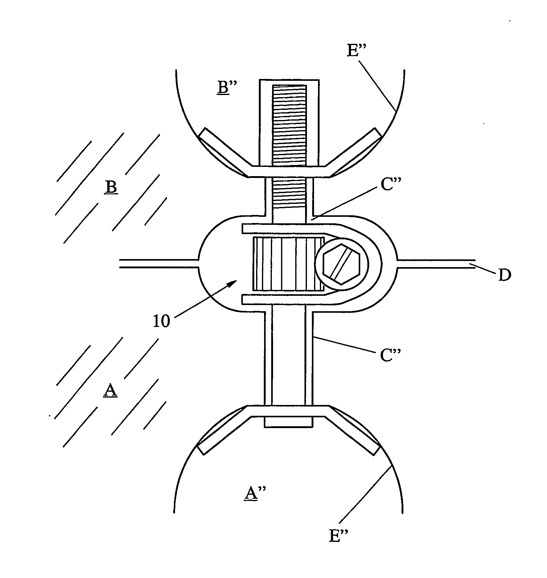
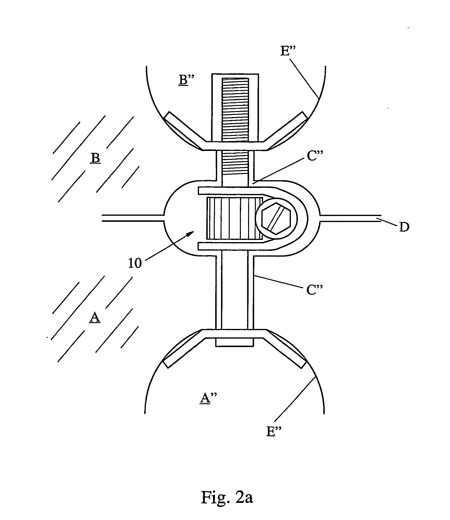
[0058] Within these cut-away portions, an adjustable clamp assembly 10 is positioned.

[0059] The clamp assembly 10 is described with reference to FIG. 2b, shown in isolation from the objects A, B, so that the details of the clamping assembly can be understood readily.

[0060] The clamp 10 includes first and second clamp members in the form of a first clamp component 30 and a second clamp component 20.

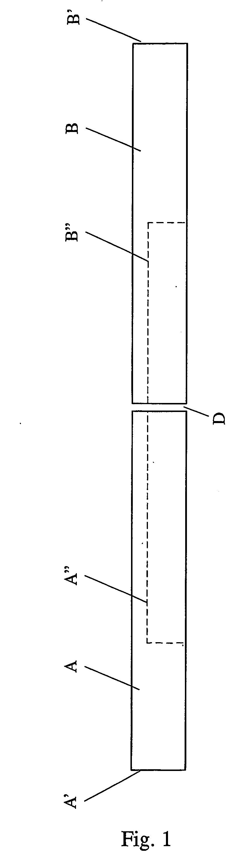
[0061] As seen in FIG. 2a, the clamp components 20, 30 are adapted to co-operatively bring together the wall surfaces E″ of the cut-out portions A″, B″. Effectively, when the clamp 10 draws the two surfaces E″ together, this draws together the two end surfaces of the objects A, B.

[0062] In FIG. 2b, the two clamping components 20, 30 have inner surfaces 21, 31 that are adapted to abut against the surfaces E″.

[0063] InFIG. 2b, the second clamp component 20 has an inner surface 21, while the first clamp component 30 has an inner surface 31.

[0064] As seen in FIG. 2b, both the inner surfac...

embodiment 10

[0081] The adjustable clamp assembly 400 operates in a similar manner to the embodiment 10, and includes first and second clamp members 430, 420 having respective facing inner surfaces 431, 421 adapted to abut against the wall surfaces E″ shown in FIG. 2a. The assembly 400 further includes an elongated connection member in the form of a cylindrical rod 440 having a threaded portion 441 at one end, to which the first clamp member 430 is connected by screw-thread engagement.

embodiment 400

[0082] A gear assembly in the form of a worm drive assembly 450 incorporates a first gear member having a worm gear 451 and a second gear member having a worm wheel 452. In the embodiment 400, the second gear member is integral with the rod 440, however in other embodiments the second gear member may be a separate component engaged with the rod 440. In either case, the key requirement is that rotation of the second gear member (worm wheel 452) results in corresponding rotation of the connection member (rod 440). The rod 440 passes through a hole in the second clamp member 420, to allow for the free rotation of the rod within the second clamp member.

[0083] Accordingly, in a manner similar to the operation of the embodiment 10, rotation of the worm gear 451 causes rotation of the rod 440, which in turn causes the inner surfaces 421, 431 of the clamp components 420, 430 to be either drawn together or apart along a path of linear motion, depending on the direction of the rotation of the...


PUM

PropertyMeasurementUnit
Forceaaaaaaaaaa
Ratioaaaaaaaaaa

Abstract

An adjustable clamp assembly (600) includes an elongated connection member (640) and a gear assembly (650). The gear assembly includes a rotatable first gear member having an axis of rotation substantially perpendicular to a longitudinal axis of the connection member (640). The gear assembly also includes a second gear member cooperatively engaged with the first gear member. The clamp assembly further includes a first clamp member (630). The elongated connection member (640), the gear assembly (650) and the first clamp member (630) are arranged such that rotation of the first gear member results in a linear motion of the first clamp member (630) parallel to the longitudinal axis of the connection member (640).

Description

FIELD OF INVENTION [0001] The present invention relates to adjustable clamps. BACKGROUND OF INVENTION [0002] An adjustable clamp is a tool which is used, for example, to draw two surfaces together in a clamping action. Also, adjustable clamps can be used to hold surfaces away from each other. [0003] A particular problem is encountered when trying to clamp together two flat surfaces, end to end. [0004] The problem can be appreciated from FIG. 1 where objects A and B are to be clamped together end to end. (The gap between objects A and B is exaggerated in FIG. 1 for clarity, but the intention is for the two objects to be clamped against each other end to end). [0005] It would be impractical to use a standard clamp, of the type which seeks to compress items positioned between its jaws. For instance in FIG. 1, it would be impractical to position a standard clamp around the end points A′ and B′, since, in practice, objects A and B are likely to be very long. Moreover, if a standard clamp...

Claims


Application Information

Patent Timeline
IPC IPC(8): B25B5/06B25B1/10B25B5/14F16B2/12F16B5/00F16B7/06F16B12/18F16B12/32F16B35/04F16B35/06
CPCB25B5/145F16B5/0092F16B12/18Y10T29/53683F16B35/045F16B35/06Y10T29/53678F16B12/32
Inventor VAN DE LOO, PAULARNOLD, AARON ANTHONYDORNEY, JARROD LEIGH
Owner RAPIDJOINT
Why Eureka
Try Eureka