Mounting system for a solar panel

a solar panel and mounting system technology, applied in the field of solar panels, can solve problems such as installation errors, and achieve the effects of reducing the possibility of installation errors, simplifying the electrical assembly of modules, and facilitating installation

Inactive Publication Date: 2005-11-24
ANDALAY SOLAR
View PDF25 Cites 143 Cited by
  • Summary
  • Abstract
  • Description
  • Claims
  • Application Information

AI Technical Summary

Benefits of technology

[0008] An integrated module frame and racking system for a solar panel is disclosed. The solar panel comprises a plurality of solar modules and a plurality of splices for coupling the plurality of solar modules together. The plurality of splices provide a way to make the connected modules mechanically rigid both during transport to the roof and after mounting for the lifetime of the system, provide wiring connections between modules, provide an electrical grounding path for the modules, provide a way to add modules to the panel, and provide a way to remove or change a defective module. Connector sockets are provided on the sides of the modules to simplify the electrical assembly of modules when the modules are connected together with splices.
[0009] A solar panel in accordance with the present invention is optimized for fast and reliable installation. In addition, the fewer parts and simpler assembly technique reduces the potential for installation error. In addition, multiple modules for the panel can be supported during transport. In addition, modules and panels can be assembled closer together, improving space usage and improving aesthetics. Furthermore, individual modules can be added to and connected with existing solar panels. In addition, the use of an integrated mounting rail allows the panel to be mounted closer to the roof, improving aesthetics. Further, a minimal number of parts are utilized for the entire assembly. Finally, solar modules can be securely stacked and shipped with pre-installed mounting brackets, reducing shipping, packing and unpacking costs.

Problems solved by technology

In addition, the fewer parts and simpler assembly technique reduces the potential for installation error.

Method used


Image

  • Mounting system for a solar panel
  • Mounting system for a solar panel
  • Mounting system for a solar panel

Examples


Embodiment Construction

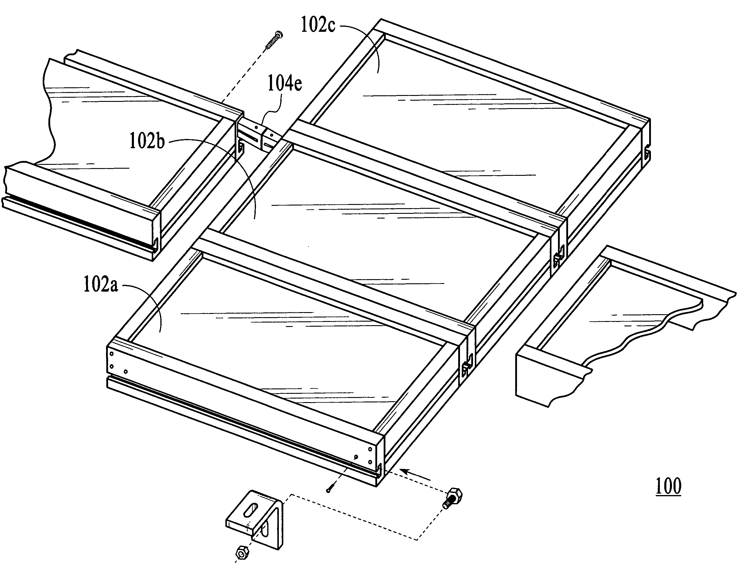
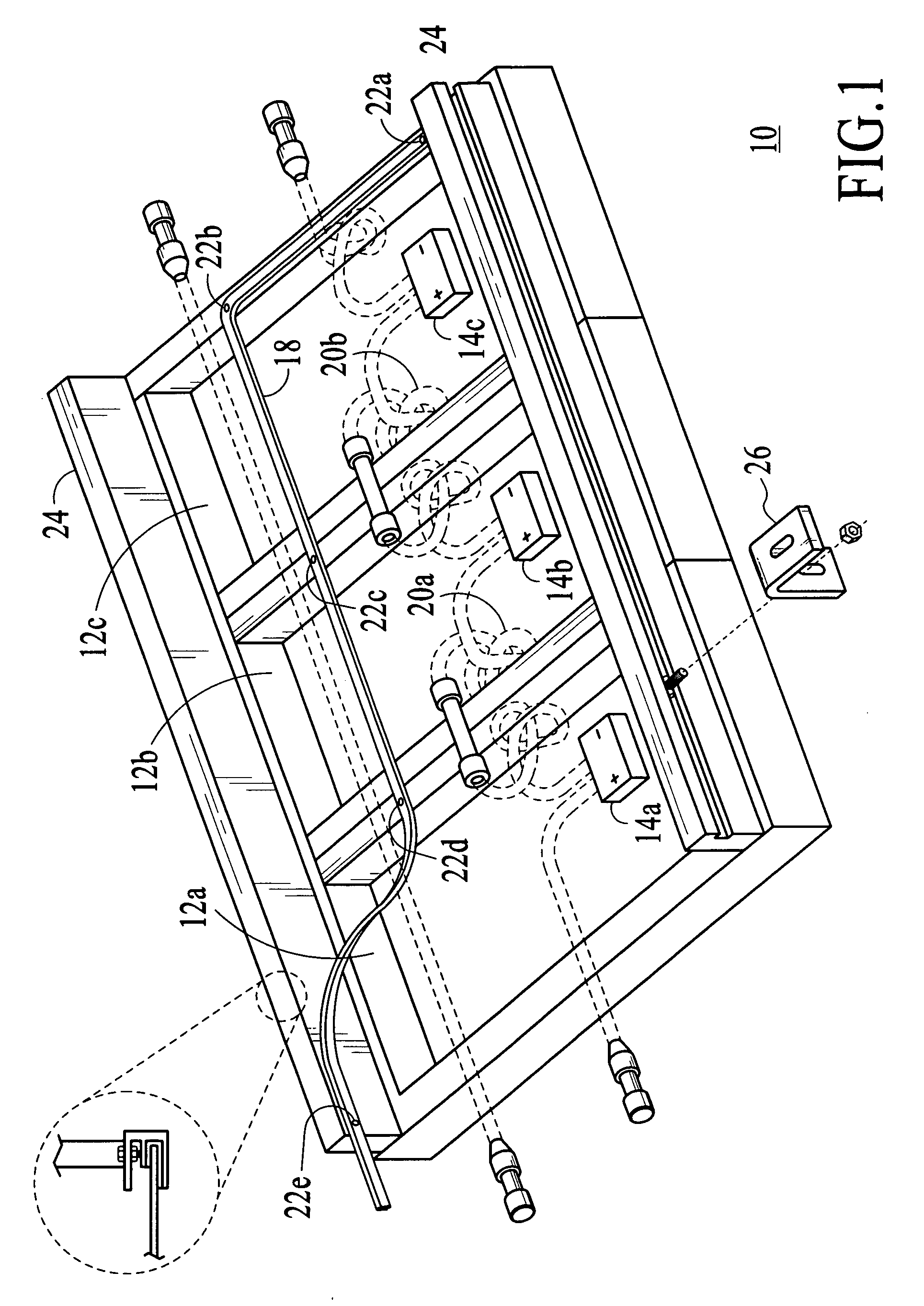
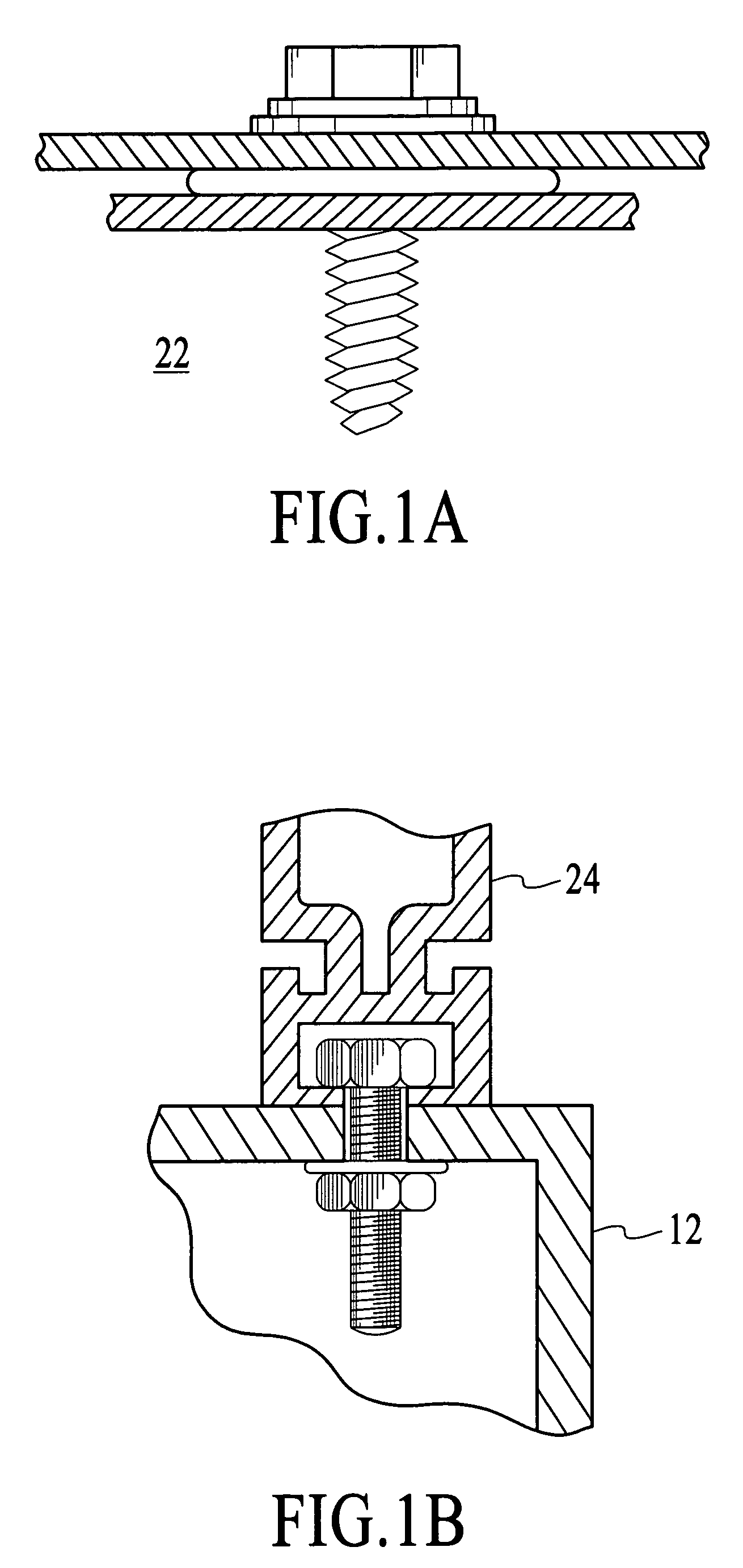
[0020] The present invention relates generally to solar panels and more particularly to a mounting system for solar panels. The following description is presented to enable one of ordinary skill in the art to make and use the invention and is provided in the context of a patent application and its requirements. Various modifications to the preferred embodiment and the generic principles and features described herein will be readily apparent to those skilled in the art. Thus, the present invention is not intended to be limited to the embodiment shown but is to be accorded the widest scope consistent with the principles and features described herein.

[0021] A system and method in accordance with the present invention provides for an integrated module frame and racking system for a solar panel. The solar panel in accordance with the present invention is optimized for fast installation on a structure with a particular emphasis on completing all installation activities from the top of th...


PUM


Abstract

An integrated module frame and racking system for a solar panel is disclosed. The solar panel comprises a plurality of solar modules and a plurality of splices for coupling the plurality of solar modules together. The plurality of splices provide a way to make the connected modules mechanically rigid both during transport to the roof and after mounting for the lifetime of the system, provide wiring connections between modules, provide an electrical grounding path for the modules, provide a way to add modules to the panel, and provide a way to remove or change a defective module. Connector sockets are provided on the sides of the modules to simplify the electrical assembly of modules when the modules are connected together with splices.

Description

FIELD OF THE INVENTION [0001] The present invention relates generally to solar panels and more particularly to an assembly and mounting system for a solar panel. BACKGROUND OF THE INVENTION [0002] Solar electric systems are the most environmentally friendly way of generating electricity. To provide such solar electric systems, typically there is a solar panel, which comprises a plurality of solar modules, which are coupled together. The solar panels are typically assembled directly on the roof of a building, assembled on the ground and then mounted on a roof of a building, or installed on a dedicated ground or pole mounted frame. FIG. 1 illustrates a conventional solar panel assembly 10. The solar panel in this embodiment comprises three solar modules, 12A-12C. However, one of ordinary skill in the art recognizes there could be any number of modules and they could be in any configuration to form a solar panel. [0003] Each of the solar panel modules 12A-12C includes a junction box 14...

Claims


Application Information

Patent Timeline
Patent Type & Authority Applications(United States)
IPC IPC(8): E04D13/18F24J2/52H01L31/042H01L31/048
CPCF24J2/4638F24J2/5211F24J2/5262F24J2002/5279Y02B10/12Y10T403/55Y02E10/47Y02E10/50H02S20/00H02S20/23Y02B10/20F24S40/85F24S2025/013F24S25/20F24S25/67Y02B10/10E04D13/00
Inventor CINNAMON, BARRY
Owner ANDALAY SOLAR
Why Eureka
Try Eureka