Steam engine
a steam engine and steam technology, applied in steam engine plants, machines/engines, mechanical equipment, etc., can solve the problems of inability to increase the fluid pressure by vaporization, the heat transfer time of the inner surface of the cooling portion to the center of the working fluid, and the output energy of the steam engine would become smaller, so as to prevent the effect of mechanical energy reduction
- Summary
- Abstract
- Description
- Claims
- Application Information
AI Technical Summary
Benefits of technology
Problems solved by technology
Method used
Image
Examples
first embodiment
[0063] A first embodiment of the present invention will now be explained with reference to the drawings.
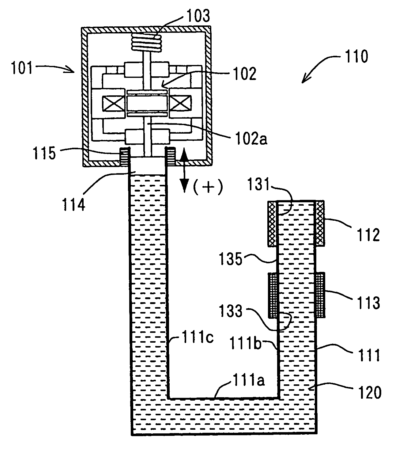
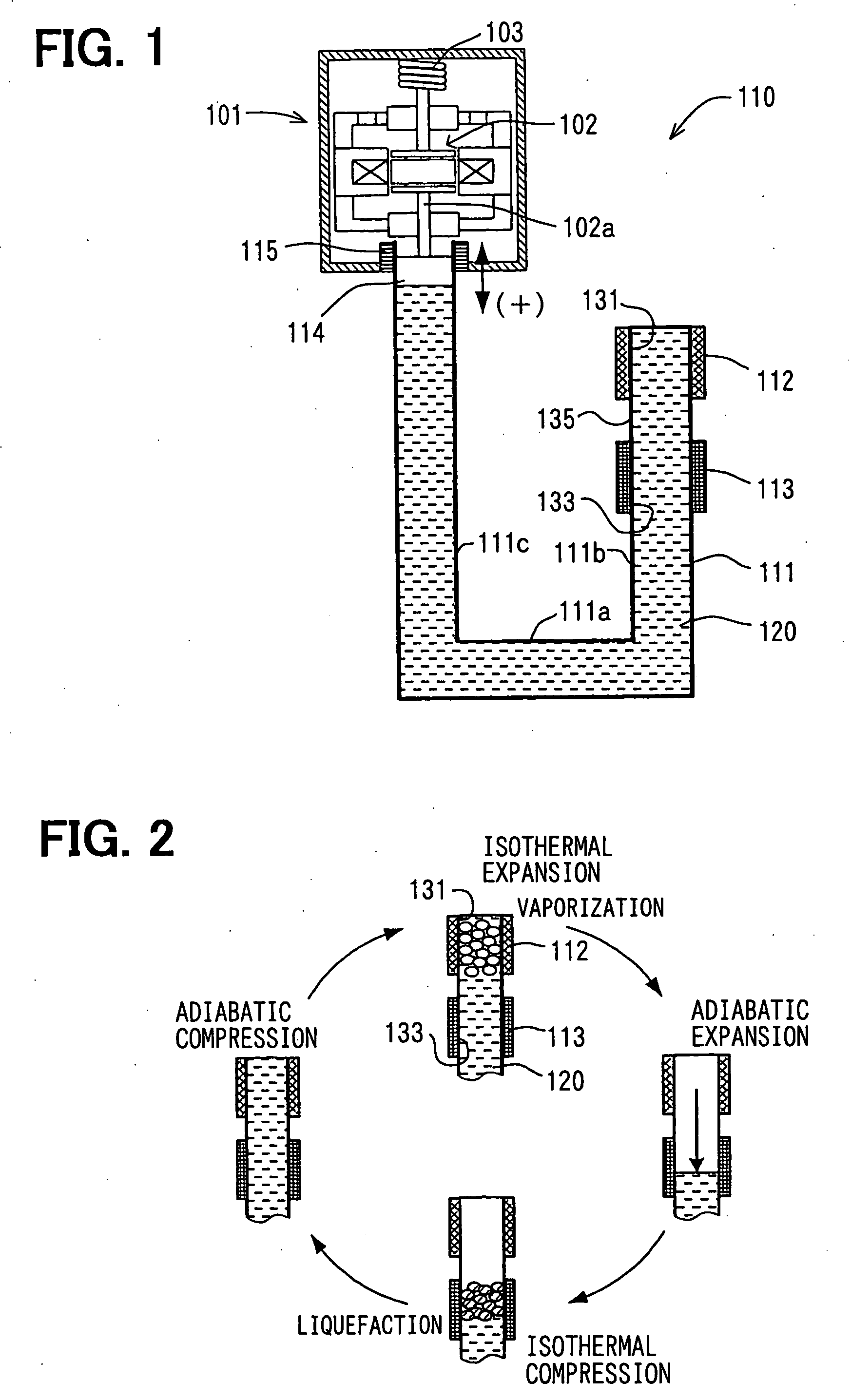
[0064] In the first embodiment shown in FIG. 1, a steam engine 110 is applied to a linear motor, in which a moving member 102 of an output device (an electric power generator) 101 is vibrated. An electric power device comprises the steam engine 110 and the electric power generator 101.
[0065] The electric power generator 101 is a linear vibration generator, in which a permanent magnet (not shown) is fixed to the moving member 102 and electromotive force is generated by vibrating (oscillating) the moving member 102.
[0066] As shown in FIG. 1, the steam engine 110 comprises a fluid container 111 in which working fluid 120 is filled with a predetermined pressure, a heating device 112 for heating the working fluid 120 in the fluid container 111, and a cooling device 113 for cooling down steam generated at the heating device 112.
[0067] The heating device 112 and the cooling device 11...
second embodiment
[0108] A second embodiment of the present invention is explained with reference to FIGS. 6 to 9, wherein the same reference numerals are used to designate the same or similar portions of the first embodiment.
[0109] In FIG. 6, a heating portion 131, a connecting portion 135 and a cooling portion 133 of a first straight pipe portion 111b are formed from multiple small pipe portions 215, and a lower part of the first straight pipe portion 111b is formed from a collecting pipe portion 216. Each of the lower ends of the small pipe portions 215 is communicated with the collecting pipe portion 216, whereas each of the upper ends of the small pipe portions 215 is closed.
[0110] A heating device 112 and a cooling device 113 are respectively formed to surround the heating portion 131 and the cooling portion 133 of the multiple small pipe portions 215.
[0111]FIG. 7 schematically shows an enlarged cross sectional view of the heating and cooling devices 112 and 113, wherein liquid surfaces of w...
third embodiment
[0134] The steam engine 110 according to a third embodiment, in which a communication portion 243 is provided to communicate the small pipe portions 215 with one another, is explained with reference to FIG. 10.
[0135] The steam engine 110 differs from the second embodiment (FIGS. 6 to 8) in a structure of a top end portion of the first straight pipe portion 111b.
[0136] A cross sectional view of the top end portion of the first straight pipe portion 111b, the heating device 112, and the cooling device 113 is shown in FIG. 10, wherein the liquid-phase working fluid 120 is pushed down by the fluid pressure of the steam in the fluid container 111.
[0137] As shown in FIG. 10, the communication portion 243 is formed at the top end of the fluid container 111 to communicat the small pipe portions 215 (at upper ends of the heating portions 131) with one another, so that an inside space of the communication portion 243 is communicated with all of the inside spaces of the small pipe portions ...
PUM
 Abstract
Description
Claims
Application Information
 - R&D
- Intellectual Property
- Life Sciences
- Materials
- Tech Scout
- Unparalleled Data Quality
- Higher Quality Content
- 60% Fewer Hallucinations
Browse by: Latest US Patents, China's latest patents, Technical Efficacy Thesaurus, Application Domain, Technology Topic, Popular Technical Reports.
© 2025 PatSnap. All rights reserved.Legal|Privacy policy|Modern Slavery Act Transparency Statement|Sitemap|About US| Contact US: help@patsnap.com


