Apparatus and method of applying force to a stuck object in a wellbore

a technology of force applied in the field of downhole tools, can solve the problems of object stuck, mechanical failure, object stuck,

Inactive Publication Date: 2005-11-24
BAKER HUGHES INC
View PDF26 Cites 21 Cited by
  • Summary
  • Abstract
  • Description
  • Claims
  • Application Information

AI Technical Summary

Problems solved by technology

In another instance, the object may be stuck due to a mechanical failure, such as, for example, a collapsed casing or production tubing.
In yet another example, the object may be stuck due to differential sticking of the object against the borehole wall.
Differential sticking typically occurs when high-contact forces, caused by low reservoir pressures, high wellbore pressures, or both, are exerted over a sufficiently large area of the drill string.
Therefore, only a limited amount of energy can be delivered to a stuck object over a given period of time, with this type of tool.
When the object is stuck in an unconsolidated material, for example, this type of loading does not produce a favorable rate of buildup of pore pressure, in the unconsolidated material in which the tubular object is stuck.
Therefore, the necessary reduction of soil strength in the area surrounding the stuck portion of the object, as a result of soil liquefaction, is not realized, and the stiction force must be overcome by a significant amount of overpull on the work string.
That is, a larger over-pull will deliver a harder blow to the stuck portion of the tubular object.
That is, this method results in a high degree of soil liquefaction and a high degree of friction force reduction, resulting in a comparatively low extraction force requirement.
However, in this method, the vibrations are commonly imparted to the tubular object at the Earth's surface, and the tool has a limited ability to propagate the vibrations to great depths in the well bore.
For example, if an object is stuck in an unconsolidated material at a depth greater than that to which the removal tool can propagate sufficient vibration energy, then this method is not effective.
Spacing the pulses more closely assists in pore pressure buildup, but the smaller pulse amplitude is generally not great enough to induce plastic strains in the soil.
As a result, the degree of soil liquefaction may be only moderate, and, therefore, the resultant reduction in the stiction force also is only moderate.

Method used


Image

  • Apparatus and method of applying force to a stuck object in a wellbore
  • Apparatus and method of applying force to a stuck object in a wellbore
  • Apparatus and method of applying force to a stuck object in a wellbore

Examples


Embodiment Construction

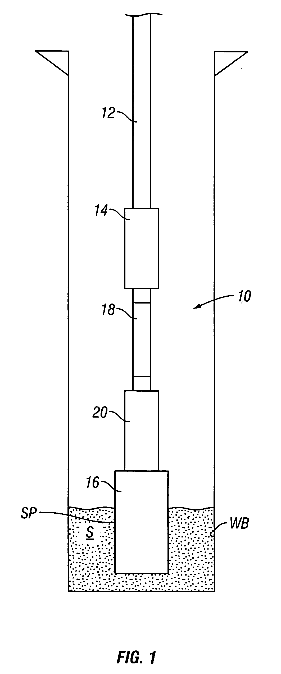
[0019]FIG. 1 shows a tubular assembly 10 which has become stuck in sand S at a location downhole in a well bore WB. The assembly 10 includes a tubular such as a work string 12, along with a vibratory apparatus 14, 18, 20, attached to the stuck object or fish 16. The well bore is illustrated as being a cased hole, but it may be either open hole or cased hole, and the sand in which the fish 16 is stuck may be a sand formation, completion sand, gravel pack, or other similar substance. The location at which the fish 16 is stuck is commonly referred to as the stuck point SP. The vibratory apparatus 14, 18, 20 which will be used to perform the method of the present invention may have been incorporated into the tubular assembly 10 before its initial tripping into the well bore, or it may be lowered on the work string 12 and attached to the fish 16 after the fish becomes stuck. In either case, the vibratory apparatus should be installed at or very near the stuck point on the fish, and the v...


PUM


Abstract

An apparatus for applying a force to a stuck object in a wellbore comprises a work string extending in the wellbore. A vibrating string has a vibrator engaged with the stuck object. The vibrator drives the vibrating string to impart the force to the stuck object. An isolator associated with the work string and the vibrating string decouples a portion of a motion of the vibrating string from the work string. A method of applying a force to a stuck object in a wellbore comprises extending a work string in the wellbore from a surface location. A vibrating string is engaged with the stuck object. The vibrating string is driven at a frequency to apply the force to the stuck object. The work string is isolated from the vibrating string such that a portion of the motion of the vibrating string is decoupled from the work string.

Description

CROSS REFERENCE TO RELATED APPLICATIONS [0001] This application is a Continuation-In-Part of U.S. patent application Ser. No. 10 / 617,195 filed Jul. 9, 2003, which is incorporated herein by reference.STATEMENT REGARDING FEDERALLY SPONSORED RESEARCH OR DEVELOPMENT [0002] Not Applicable BACKGROUND OF THE INVENTION [0003] 1. Field of the Invention [0004] The present invention is in the field of downhole tools used in oil and gas well drilling and downhole equipment recovery. More specifically, it is an apparatus and method for loosening a stuck object by imparting vibration to the object. [0005] 2. Background Art [0006] In well operation, there is often a need for jarring, impact or vibration devices to move tubular objects that are stuck in a well bore, as a result, for example, of excessive friction with sand, or other materials, at a downhole location, often called “sticktion” or “stiction” force. The stuck object may be a work string, a production tube, or a drill string. It may be ...

Claims


Application Information

Patent Timeline
Patent Type & Authority Applications(United States)
IPC IPC(8): E21B28/00E21B31/00
CPCE21B31/005
Inventor MODY, RUSTOM K.SONI, MOHAN L.STOESZ, CARL W.
Owner BAKER HUGHES INC
Why Eureka
Try Eureka