Automatic drag brake for a power take-off unit output shaft

a technology of automatic drag brake and power take-off unit, which is applied in the direction of mechanical equipment, agricultural machines, gearing, etc., can solve the problems of insufficient frictional braking surface available to ensure complete rotational stoppage, the output shaft of the pto unit to continue to be at least partially rotatably driven, and the insufficient frictional braking surface to ensure the effect of complete rotational stoppag

Active Publication Date: 2005-11-24
PARKER INTANGIBLES LLC
View PDF19 Cites 16 Cited by
  • Summary
  • Abstract
  • Description
  • Claims
  • Application Information

AI Technical Summary

Benefits of technology

[0023] In yet a differing version, in the disengaged position, the bias of the spring member overcomes the fluid pressure within the cavity, thereby axially moving the brake disc into contact with the second reaction member and thus retarding rotation of the output shaft.

Problems solved by technology

Conversely, when the clutch assembly is disengaged, the output shaft is decoupled from the input gear and the driven device is not operated by the engine, etc.
Since operation of the PTO unit can generate undesirable friction and heat, the PTO unit is generally provided with a considerable quantity of lubricating fluid.
However, it has been determined that the relatively viscous nature of the lubricating fluid can cause the output shaft to continue to be at least partially rotatably driven, even though the clutch assembly has been disengaged.
Naturally, such rotation of the output shaft of the PTO unit, after the clutch assembly has been disconnected, is undesirable.
While workable, it has been determined that the available frictional braking surface is not sufficient to ensure complete rotational stoppage of the output shaft under all operating conditions.
However, none of these prior art structures, pertains to the use of a cone-type brake, having interacting truncating frusto-conical mating surfaces, where the stationary reaction member, having one of the noted frusto-conical surfaces, is located on the inner surface of the inside diameter of one of the PTO unit bearing end caps.

Method used


Image

  • Automatic drag brake for a power take-off unit output shaft
  • Automatic drag brake for a power take-off unit output shaft
  • Automatic drag brake for a power take-off unit output shaft

Examples


Embodiment Construction

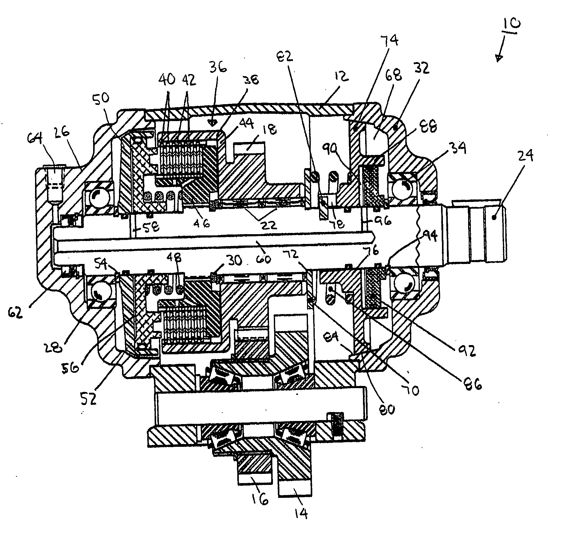
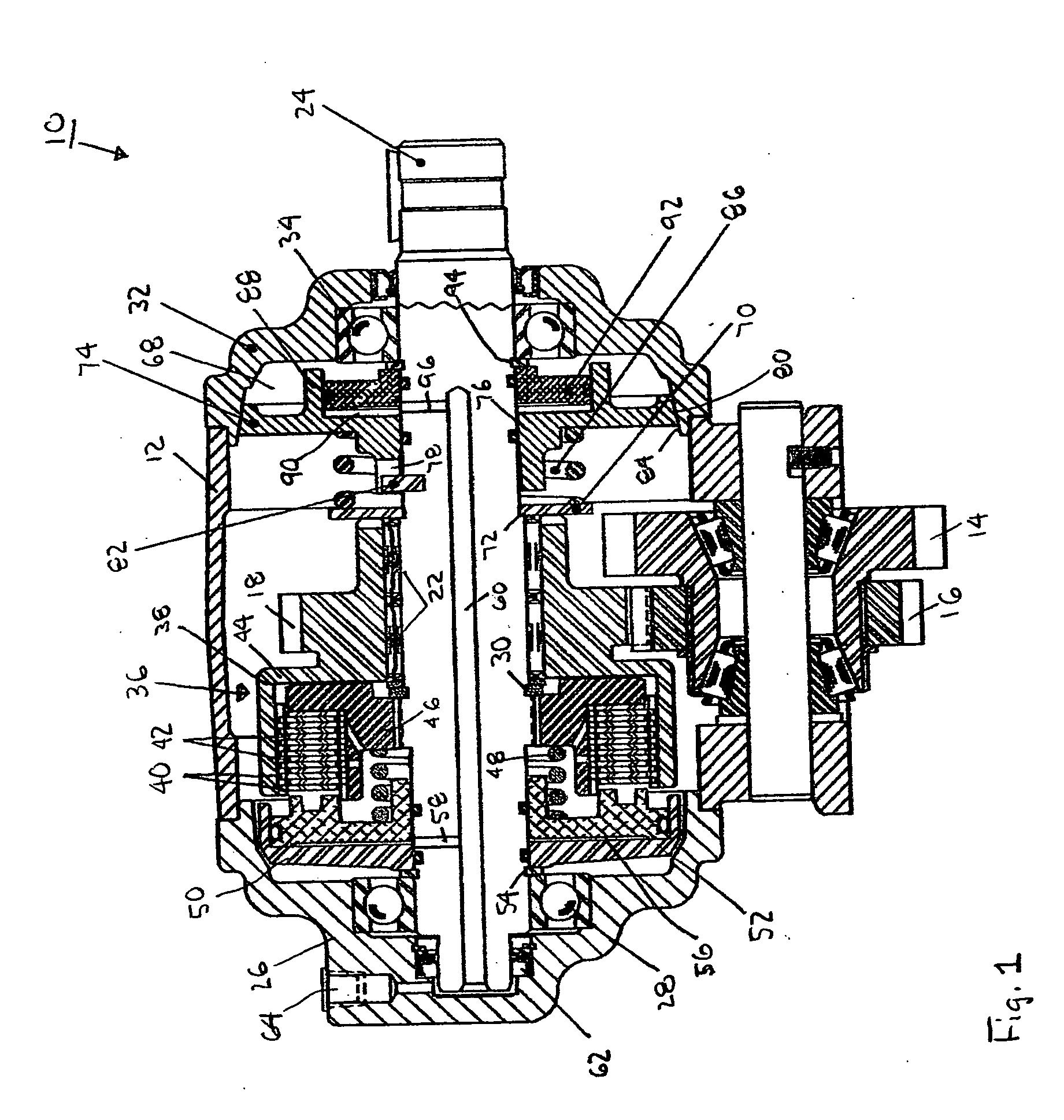
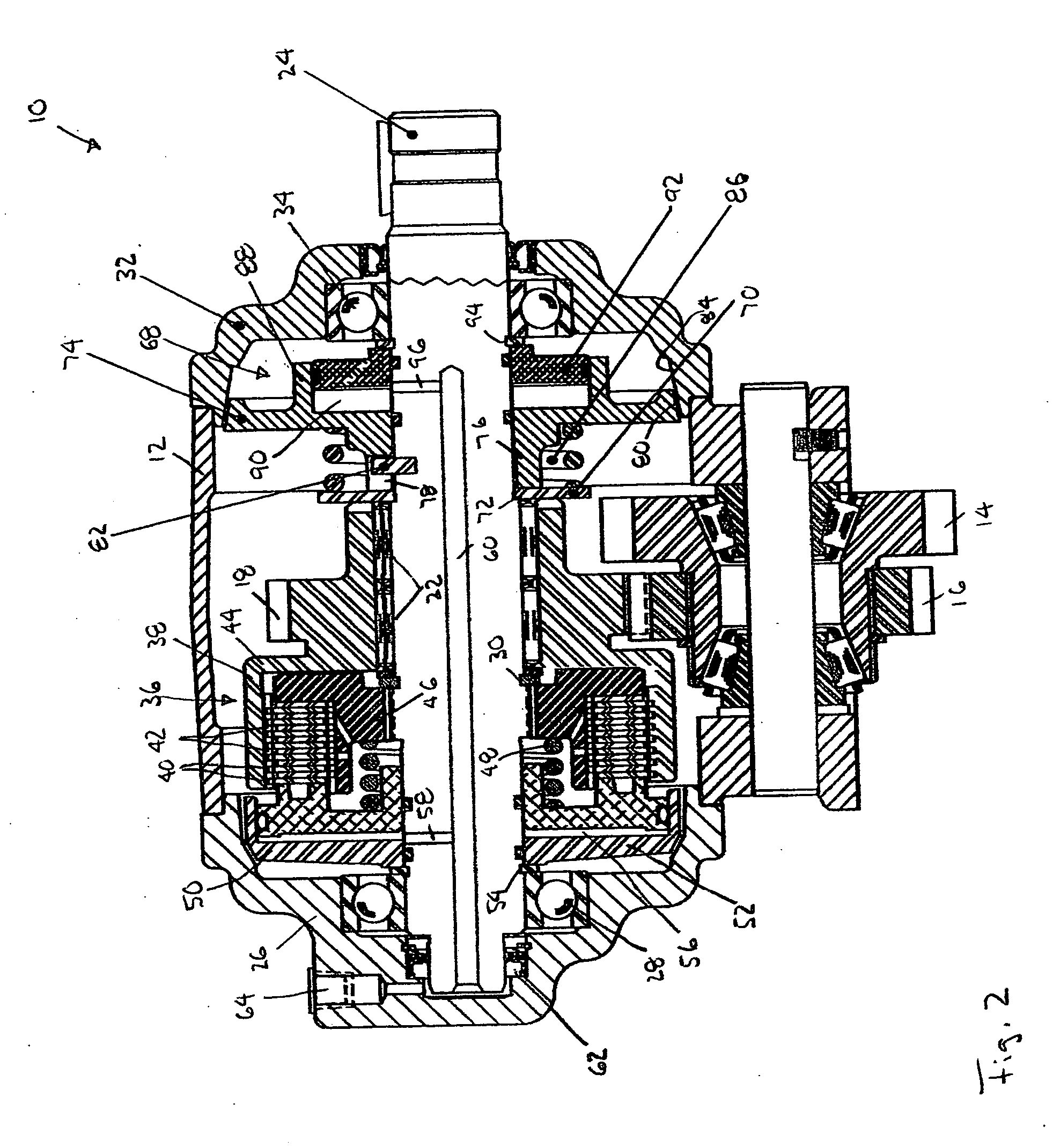
[0036] Referring now to the several drawings, illustrated in FIG. 1 is a power take-off (PTO) unit, generally indicated at 10. Since the basic structure, mode of operation and function of PTO unit 10 are well known in the art, in the interest of brevity, only those portions thereof that are necessary for a complete understanding of the invention will be described in detail hereinafter. PTO unit 10 includes a rigid housing 12 that contains a rotatably journalled outside driving gear 14 operatively coupled to an input gear 16, which in turn is in meshed engagement with an inside drive gear 18 that is rotatably journalled, such as via adjacent needle bearings 22, on an output shaft 24. One end of output shaft 24 is rotatably journalled via conventional rolling element bearings 28 located within a recess in a first or closed bearing cap 26 secured to one side of PTO housing 12, with the other end of output shaft 24 being similarly journalled, via bearing 34 located within a recess forme...


PUM


Abstract

Improvement in a drag brake assembly for a power take-off unit, for use on trucks and the like, including a first reaction member axially located on an output shaft thereon; a brake disc rotatably affixed to and axially movable on the output shaft; a second reaction member forming an inner surface portion of one of the bearing caps; and a spring member interposed between the first reaction member and the brake disc, for normally biasing the brake disc into an engaged position wherein the brake disc engages the second reaction member inner surface portion, with the brake disc including a first frusto-conical outer surface portion and the second reaction member inner surface being provided with a complementary second frusto-conical surface, with the engagement therebetween keeping the output shaft from rotating.

Description

FIELD OF THE INVENTION [0001] The present invention pertains to a power take-off unit, for use on trucks and the like, including a fluid pressure actuated clutch assembly for selectively driving a vehicle accessory from a source of rotational power, such as a prime mover or transmission. More particularly, the invention pertains to an improved drag brake assembly that is automatically engaged when an associated fluid pressure actuated clutch assembly is disengaged, and further that is automatically disengaged when the clutch assembly is engaged. BACKGROUND OF THE INVENTION [0002] Power take-off (PTO) units are well known in the art and most commonly used with sources of rotational power, such as engines and transmissions, for rotatably driving an accessory such as a pump which, in turn then operates any number of hydraulically driven devices such as lifting devices, winches, and the like. [0003] Frequently, the PTO unit further includes a clutch assembly, generally of the fluid pres...

Claims


Application Information

Patent Timeline
Patent Type & Authority Applications(United States)
IPC IPC(8): A01B71/06F16D59/02F16D67/04
CPCF16D59/02A01B71/06
Inventor GRAVES, DAMON BYRON
Owner PARKER INTANGIBLES LLC
Why Eureka
Try Eureka