Permanent magnet rotary motor

a permanent magnet, rotary motor technology, applied in the direction of dynamo-electric machines, magnetic circuit rotating parts, magnetic circuit shape/form/construction, etc., can solve the problems of reducing torque, reducing motor productivity, and reducing torque, so as to reduce torque and reduce torque. the effect of greatly reducing the torqu

Inactive Publication Date: 2005-11-24
SANYO DENKI CO LTD
View PDF11 Cites 17 Cited by
  • Summary
  • Abstract
  • Description
  • Claims
  • Application Information

AI Technical Summary

Benefits of technology

[0014] In the permanent magnet rotary motor according to the present invention, the pair of end surfaces of each permanent magnet in the peripheral direction of the rotor core or the rotor shaft is formed to be substantially parallel to the virtual plane that extends in the radial direction of the rotor core or the rotor shaft, passing through the center of the stator core and the center of the arc surface. Thus, the cogging torque can be greatly reduced without greatly reducing the torque.

Problems solved by technology

Such cogging torque hinders smooth rotation or reciprocation of the motor, thus causing vibration and speed variation of the motor.
However, formation of the skew may reduce the torque or reduce the productivity of the motor.
Further, use of the permanent magnet of the eccentric type cannot increase the magnetic flux density of the motor, so that higher torque. density cannot be achieved.
However, just by using the permanent magnet of a type in which both ends in the peripheral direction of each permanent magnet are inclined, and just by setting the relationship between the open angles Am and As as described above, there was a limitation of reducing the cogging torque though the torque can be maintained to be comparatively high.

Method used


Image

  • Permanent magnet rotary motor
  • Permanent magnet rotary motor
  • Permanent magnet rotary motor

Examples


Embodiment Construction

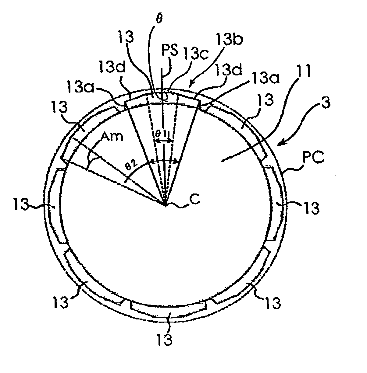
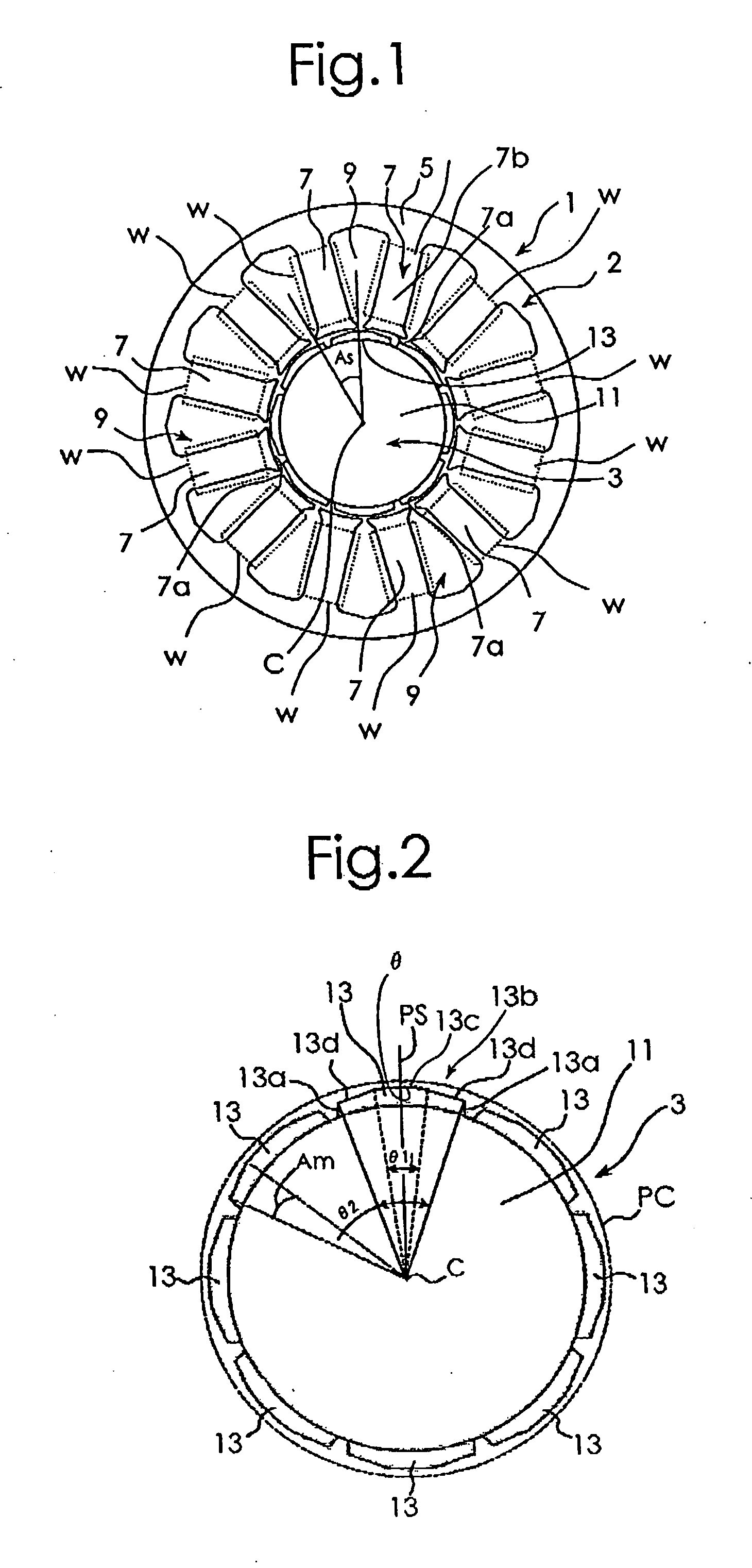
[0020] A best mode for carrying out the present invention will be described with reference to the appended drawings. FIG. 1 is a diagram schematically showing a configuration of and a relationship between a stator 1 and a rotor 3 of a permanent magnetic rotary motor used for explaining an embodiment of the present invention. In FIG. 1, for simplicity of illustration, exciting windings for the stator 1 are not illustrated. FIG. 2 is a diagram schematically showing a configuration of the rotor 3 of the permanent magnet rotary motor in FIG. 1. FIG. 2 illustrates a virtual cylindrical surface PC, which will be described later. As shown in FIG. 1, the stator 1 includes a stator core 2 and the exciting windings W. The stator core 2 includes a cylindrical yoke 5 and N (being 12, herein) magnetic pole sections 7 that extend toward a center C of the stator core 2 from the inner periphery of the yoke 5. Each of the 12 magnetic pole sections 7 has a magnetic pole main body section 7b with an e...


PUM


Abstract

There is provided a permanent magnet rotary motor that can maintain higher torque density and can also reduce cogging torque more greatly than a conventional permanent magnet rotary motor. A pair of end surfaces of each of permanent magnets used for a rotor are substantially parallel to a virtual plane that extends in the radial direction of a rotor core while passing through the centers of a stator core and an arc surface. Then, the length of the arc surface in the peripheral direction of a rotor core and inclinations of inclined surfaces are so determined that a pole arc ratio Ψ1 of the arc surface and a pole arc ratio ψ2 of a magnetic pole surface in each permanent magnet satisfy the relation of P/2N≦Ψ2−Ψ1≦1.38×P/2N.

Description

BACKGROUND OF THE INVENTION [0001] The present invention relates to a permanent magnet rotary motor. [0002] Generally, there is known a permanent magnet rotary motor which has armatures to generate a shifting magnetic field at a stator and a plurality of magnetic poles composed of permanent magnets at a rotor, which act with the shifting magnetic field to generate an electromagnetic force. However, in the motor with the permanent magnets as described above, pulsating torque (cogging torque) and a thrust force are produced at the time of no-load operation. Such cogging torque hinders smooth rotation or reciprocation of the motor, thus causing vibration and speed variation of the motor. As an approach to reducing the cogging torque, there have been hitherto proposed formation of a slot with an oblique groove, hereinafter referred to as a skew, in a stator or a rotor, or use of a permanent magnet having the shape of a sector with the center of an inner circular arc thereof not aligned ...

Claims


Application Information

Patent Timeline
Patent Type & Authority Applications(United States)
IPC IPC(8): H02K1/22H02K1/27H02K21/14H02K29/03
CPCH02K1/278H02K29/03H02K21/14
Inventor MIYASHITA, TOSHIHITOONODERA, SATORU
Owner SANYO DENKI CO LTD
Why Eureka
Try Eureka