Stator of dynamoelectric machine and method for manufacturing stator winding

a technology of stator winding and dynamoelectric machine, which is applied in the direction of magnetic circuit rotating parts, magnetic circuit shape/form/construction, magnetic bodies, etc., can solve the problems of poor electrical insulation properties, damage to the electrically-insulating coating of the conductor wire, and difficulty in achieving a high degree of flatness on the long sides of each of the flattening slot-housed portions

Inactive Publication Date: 2005-11-24
MITSUBISHI ELECTRIC CORP
View PDF6 Cites 39 Cited by
  • Summary
  • Abstract
  • Description
  • Claims
  • Application Information

AI Technical Summary

Benefits of technology

[0015] According to another aspect of the present invention, there is provided a method for manufacturing a dynamoelectric stator including a cross section flattening process in which slot-housed portions having a circular cross section are i

Problems solved by technology

However, in the conventional method for manufacturing the stator 1, because six slot-housed portions 12a having a circular cross section are stacked in a single column and deformed by pressing them simultaneously with a pusher 17, the slot-housed portions 12a having a circular cross section are flattened while being in direct contact with each other, making it difficult to achieve a high degree of flatness on the long sides of each of the fla

Method used


Image

  • Stator of dynamoelectric machine and method for manufacturing stator winding
  • Stator of dynamoelectric machine and method for manufacturing stator winding
  • Stator of dynamoelectric machine and method for manufacturing stator winding

Examples


embodiment 1

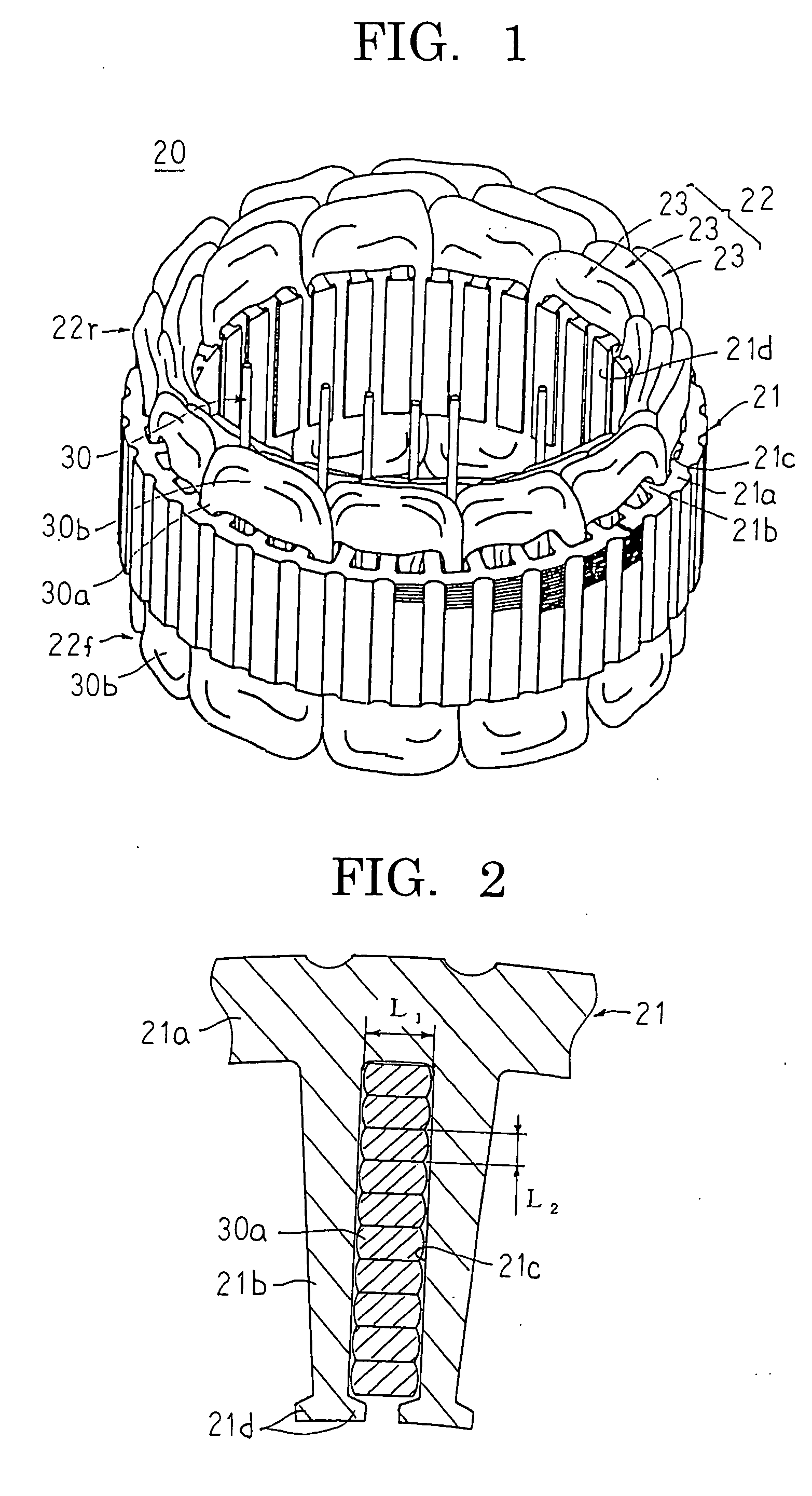
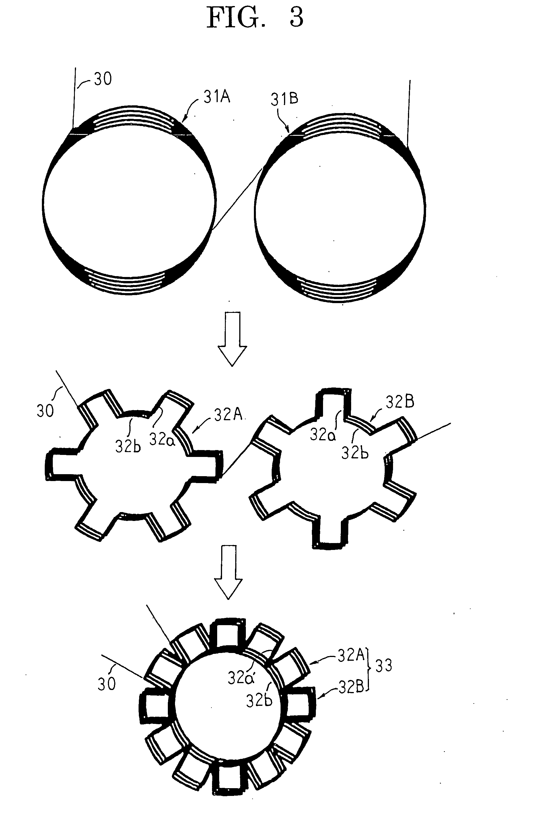
[0034]FIG. 1 is a perspective showing a dynamoelectric stator according to Embodiment 1 of the present invention, FIG. 2 is a partial cross section showing a slot-housed state of a stator winding in the dynamoelectric stator according to Embodiment 1 of the present invention, FIG. 3 is a process diagram explaining a process for manufacturing a star-shaped winding unit in a method for manufacturing the dynamoelectric stator according to Embodiment 1 of the present invention, FIG. 4 is a process diagram explaining a cross section flattening process for slot-housed portions of the star-shaped winding unit in the method for manufacturing the dynamoelectric stator according to Embodiment 1 of the present invention, FIG. 5 is a perspective showing a distributed winding unit in the dynamoelectric stator according to Embodiment 1 of the present invention, FIG. 6 is a partial enlargement showing the distributed winding unit in the dynamoelectric stator according to Embodiment 1 of the presen...

embodiment 2

[0062]FIG. 10 is a partial cross section showing a slot-housed state of a stator winding in a dynamoelectric stator according to Embodiment 2 of the present invention.

[0063] In FIG. 10, in a stator core 21A, a cross section of the tooth portions 21b′ perpendicular to a central axis of the stator core 21A is formed in a generally rectangular shape, and a cross section of slots 21c′ has a generally trapezoidal shape tapering radially inward. An aspect ratio (L2 / L1) of slot-housed portions 30a housed in the slots 21c′ so as to line up in single columns in a radial direction is larger in the slot-housed portions 30a positioned on an inner radial side so as to match the shape of the slots.

[0064] Moreover, the rest of this embodiment is constructed in a similar manner to Embodiment 1 above.

[0065] A method for manufacturing a stator according to Embodiment 2 will now be explained.

[0066] First, first and second star-shaped winding units 32A and 32B are prepared in a similar manner to Em...

embodiment 3

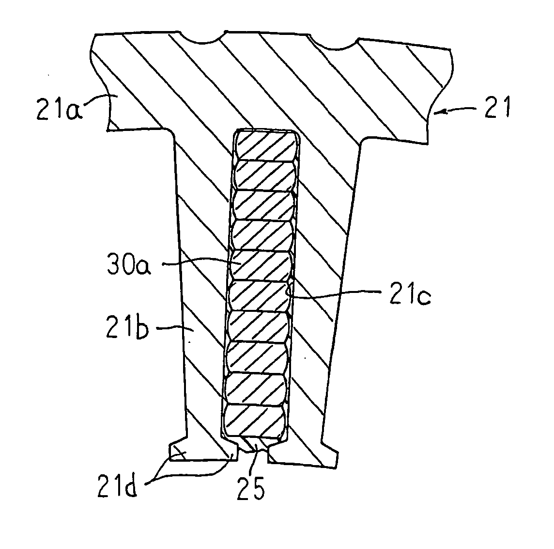
[0074]FIG. 11 is a partial cross section showing a slot-housed state of a stator winding in a dynamoelectric stator according to Embodiment 3 of the present invention.

[0075] In FIG. 11, slots 21c housing slot-housed portions 30a are impregnated with a varnish 25.

[0076] Moreover, the rest of this embodiment is constructed in a similar manner to Embodiment 1 above.

[0077] According to Embodiment 3, because the slots 21c are impregnated with the varnish 25, the varnish 25 penetrates the gaps between the slot-housed portions 30a and the slots 21c. The slot-housed portions 30a are prevented from moving inside the slots 21c, eliminating the occurrence of damage to the electrically-insulating coating resulting from the slot-housed portions 30a and the inner circumferential side surfaces of the slots 21c rubbing against each other due to vibrations from the engine, etc., of a vehicle, thereby significantly improving electrical insulation properties.

[0078] Moreover, in each of the above e...


PUM

PropertyMeasurementUnit
Fractionaaaaaaaaaa
Fractionaaaaaaaaaa
Pressureaaaaaaaaaa

Abstract

The present invention provides a dynamoelectric stator and a method for the manufacture thereof enabling electrical insulation properties to be improved by forming slot-housed portions with a racetrack-shaped cross section to suppress damage to an electrically-insulating coating arising during mounting of a stator winding to a stator core. The construction is such that the slot-housed portions of the stator winding are formed with the racetrack-shaped cross section, and are housed inside slots so as to line up in single columns in a radial direction with a longitudinal direction of the cross section of the slot-housed portions aligned in a circumferential direction. Thus, because short sides of the slot-housed portions facing inner circumferential side surfaces of the slots form convex curved surfaces, the occurrence of damage to the electrically-insulating coating resulting from rubbing between the short sides of the slot-housed portions and the inner circumferential side surfaces of the slots during insertion of the slot-housed portions into the slots is suppressed, thereby improving electrical insulation properties.

Description

TECHNICAL FIELD [0001] The present invention relates to a dynamoelectric stator and a method for manufacturing a stator winding therefor mounted to an automotive vehicle such as a passenger car, a truck, an electric train, etc., and particularly to a stator winding and a method for manufacture thereof enabling damage to an electrically-insulating coating resulting from contact between slot-housed portions of the stator winding and inner circumferential side surfaces of slots to be reduced. BACKGROUND ART [0002]FIG. 12 is a cross section explaining a conventional dynamoelectric stator construction such as that described in Japanese Patent Laid-Open No. SHO 63-194543 (Gazette), for example, and FIGS. 13 to 17 are all diagrams explaining a method for manufacturing the conventional dynamoelectric stator. [0003] This conventional dynamoelectric stator 1, as shown in FIG. 12, includes: a stator core 2; and a stator winding 4 installed in the stator core 2. [0004] The stator core 2 is cons...

Claims


Application Information

Patent Timeline
IPC IPC(8): H02K3/12H02K15/04
CPCH02K3/12Y10T29/49073H02K15/045H02K15/0485H02K3/04H02K15/04
Inventor OOHASHI, ATSUSHITAKIZAWA, TAKUSHIOHNISHI, YUKIYOSHI
Owner MITSUBISHI ELECTRIC CORP
Why Eureka
Try Eureka