

Plasma display apparatus and driving method thereof
a technology of display apparatus and plasma, which is applied in the direction of packaging foodstuffs, instruments, packaged goods, etc., can solve the problems of insufficient wall charge formation and generation of discharg
- Summary
- Abstract
- Description
- Claims
- Application Information
AI Technical Summary
Benefits of technology
Problems solved by technology
Method used
Image

Examples
first embodiment
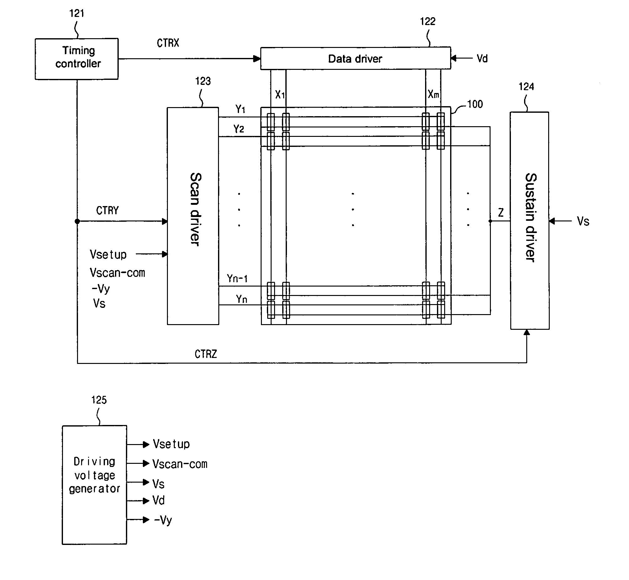
[0089]FIG. 9 is a view illustrating a driving method of the plasma display apparatus according to the present invention.
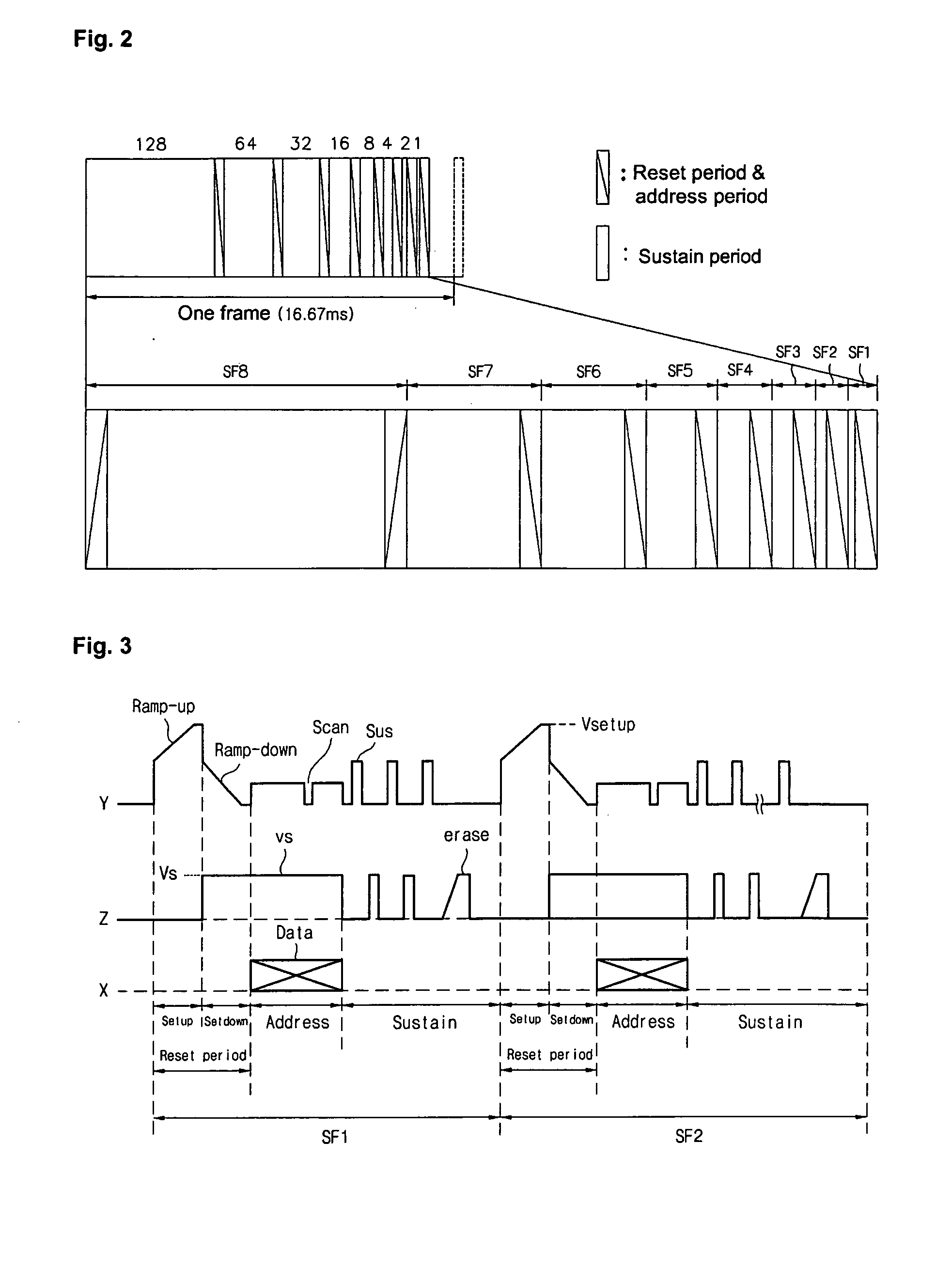
[0090] Referring to FIG. 9, the inventive PDP is driven by dividing each subfield into a reset period for initializing a whole screen, an address period for selecting a cell, and a sustain period for sustaining a discharge of the selected cell.
[0091] In a setup period of the reset period, the ramp-up waveform (Ramp-up) is concurrently applied to all scan electrodes (Y). The ramp-up waveform (Ramp-up) generates a weak discharge (setup discharge) within the cells of the whole screen, thereby generating the wall charge within the cells. In a set down period, after the ramp-up waveform is supplied, the ramp-down waveform (Ramp-down) falling from a positive voltage lower than a peak voltage of the ramp-up waveform (Ramp-up) is concurrently applied to the scan electrodes (Y). The ramp-down waveform (Ramp-down) generates a weak erasure discharge within the cells, thereby...
second embodiment
[0096] Meantime, the sustain pulse supplied at an initial half of the sustain period can be set variously. For example, in the present invention, at least one second sustain pulse (Sus2) is supplied at the initial half of the sustain period, thereby stabilizing the sustain discharge. For example, as shown in FIG. 10 for describing a driving method of the plasma display apparatus according to the present invention, the second sustain pulse (Sus2) can be supplied to the first sustain pulse (Sus1) supplied to the scan electrodes (Y) and the sustain electrode (Z). If so, the strong sustain discharge can be generated by the second sustain pulse, thereby stabilizing a subsequent sustain discharge.
third embodiment
[0097]FIG. 11 is a view illustrating a driving method of the plasma display apparatus according to the present invention. It is assumed that in the PDP, the unstable sustain discharge is generated within the discharge cells having an experimentally earlier scan sequence.
[0098] Referring to FIG. ii, the inventive PDP is driven by dividing each subfield into a reset period for initializing a whole screen, an address period for selecting the cell, and a sustain period for sustaining a discharge of the selected cell.
[0099] The reset period and the address period are the same as those of the driving method of FIG. 9 and therefore, their detailed description will be omitted.
[0100] During the sustain period, different sustain pulses are supplied to the scan electrodes. First, the second sustain pulse (Sus2) is supplied to a plurality of scan electrodes (Y1, Y2, . . . ) (for example, at least two scan electrodes) including a first scan electrode (Y1) having an earlier scan sequence. If so...
PUM
 Abstract
Description
Claims
Application Information