Eureka AIR delivers breakthrough ideas for toughest innovation challenges, trusted by R&D personnel around the world.

Display device and demultiplexer

Active Publication Date: 2005-11-24
SAMSUNG DISPLAY CO LTD
View PDF42 Cites 34 Cited by
  • Summary
  • Abstract
  • Description
  • Claims
  • Application Information

AI Technical Summary

Benefits of technology

[0016] Accordingly, it is an aspect of the present invention to provide a display device and a demultiplexer, in which the demultiplexer is provided between a data driver and a panel, and a stationary pattern due to demultiplexing is reduced or eliminated. The display device, for example, can be an organic electroluminescent display.

Problems solved by technology

The passive matrix type organic electroluminescent display can be easily realized because of its relatively simple structure, but is not suitable for realizing a large-sized screen because it consumes much more power and the time allotted to drive each light emitting device is shortened.
The active matrix type organic electroluminescent display has a relatively complicated structure, but it consumes relatively little power and the time allotted to drive each organic electroluminescent device is relatively longer.
On the other hand, even though the data driver 13 is realized as a chip separately from the panel 11, when the number of data lines is increased, the number of pins for the data driver 13 and the number of interconnection lines connecting the data driver 13 and the panel 11 should be increased in proportion to the number of data lines, thereby increasing production costs and circuit mounting space needed.

Method used


Image

  • Display device and demultiplexer
  • Display device and demultiplexer
  • Display device and demultiplexer

Examples


Embodiment Construction

[0029] Hereinafter, exemplary embodiments according to the present invention will be described in detail with reference to the accompanying drawings, wherein the display device according to the present invention is not limited to the following embodiments disclosed herein. The display device can be an organic electroluminescent display, for example.

[0030] Hereinbelow, an organic electroluminescent display according to an exemplary embodiment of the present invention will be described with reference to FIGS. 3 through 9.

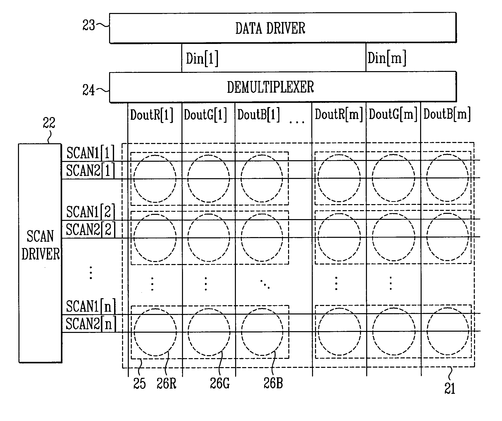
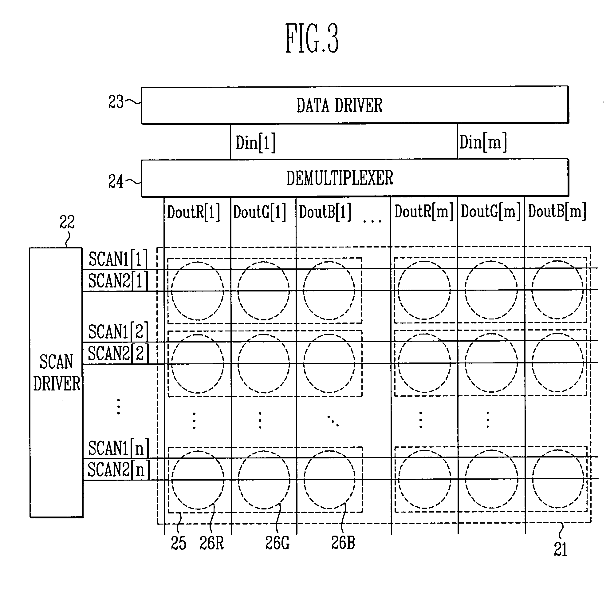
[0031]FIG. 3 is a circuit diagram of an organic electroluminescent display having an active matrix of n×m pixels according to an exemplary embodiment of the present invention.

[0032] Referring to FIG. 3, an organic electroluminescent display according to an exemplary embodiment of the present invention includes a panel 21, a scan driver 22, a data driver 23, and a demultiplexer 24.

[0033] The panel 21 includes n×m pixels 25; n first scan lines SCAN1[1], SCAN1[2], . ...


PUM


Abstract

A display device including plural pixels, plural scan lines for applying scan signals to the pixels, plural first data lines for transmitting first data currents to the pixels, a scan driver for outputting the scan signals, a demultiplexer including plural demultiplexing circuits for demultiplexing second data currents into the first data currents, and for transmitting the first data currents to the plural first data lines, and a data driver for transmitting the second data currents. A demultiplexing circuit demultiplexes one of the second data currents into at least two first data currents, and transmits them to at least two first data lines. The number of the at least two first data lines is an integer multiple of the number of sub-pixels in each pixel. A display device and a demultiplexer having a simple structure data driver, where a stationary pattern due to demultiplexing is reduced or eliminated, can be provided.

Description

CROSS-REFERENCE TO RELATED APPLICATIONS [0001] This application claims priority to and the benefit of Korean Patent Application No. 10-2004-0034560, filed May 15, 2004, in the Korean Intellectual Property Office, the entire disclosure of which is incorporated herein by reference. BACKGROUND [0002] 1. Field of the Invention [0003] The present invention relates to a display device and a demultiplexer, and more particularly to an organic electroluminescent display and a demultiplexer, in which a stationary pattern such as a horizontal pattern or a vertical pattern does not arise. [0004] 2. Discussion of Related Art [0005] An organic electroluminescent display is based on a phenomenon that an exciton emits light of a specific wavelength in an organic thin film, wherein the exciton is formed by recombination of an electron and a hole injected from a cathode and an anode, respectively. The organic electroluminescent display includes a self-emitting device, unlike a liquid crystal display ...

Claims


Application Information

Patent Timeline
IPC IPC(8): G09G3/30G09G3/32G09G5/02
CPCG09G3/325G09G3/3275G09G5/02G09G2320/0233G09G2300/0861G09G2310/0297G09G2300/0842G09G3/30
Inventor SHIN, DONG-YONG
Owner SAMSUNG DISPLAY CO LTD
Why Eureka
Eureka Blog
Learn More