Two-panel liquid-crystal-on-silicon color management system

Inactive Publication Date: 2005-11-24
JDS UNIPHASE CORP
View PDF12 Cites 54 Cited by
  • Summary
  • Abstract
  • Description
  • Claims
  • Application Information

AI Technical Summary

Problems solved by technology

However this system is still not as bright as a three-panel system since some form of temporal color sequencing is still needed.
Nevert

Method used


Image

  • Two-panel liquid-crystal-on-silicon color management system
  • Two-panel liquid-crystal-on-silicon color management system
  • Two-panel liquid-crystal-on-silicon color management system

Examples


Embodiment Construction

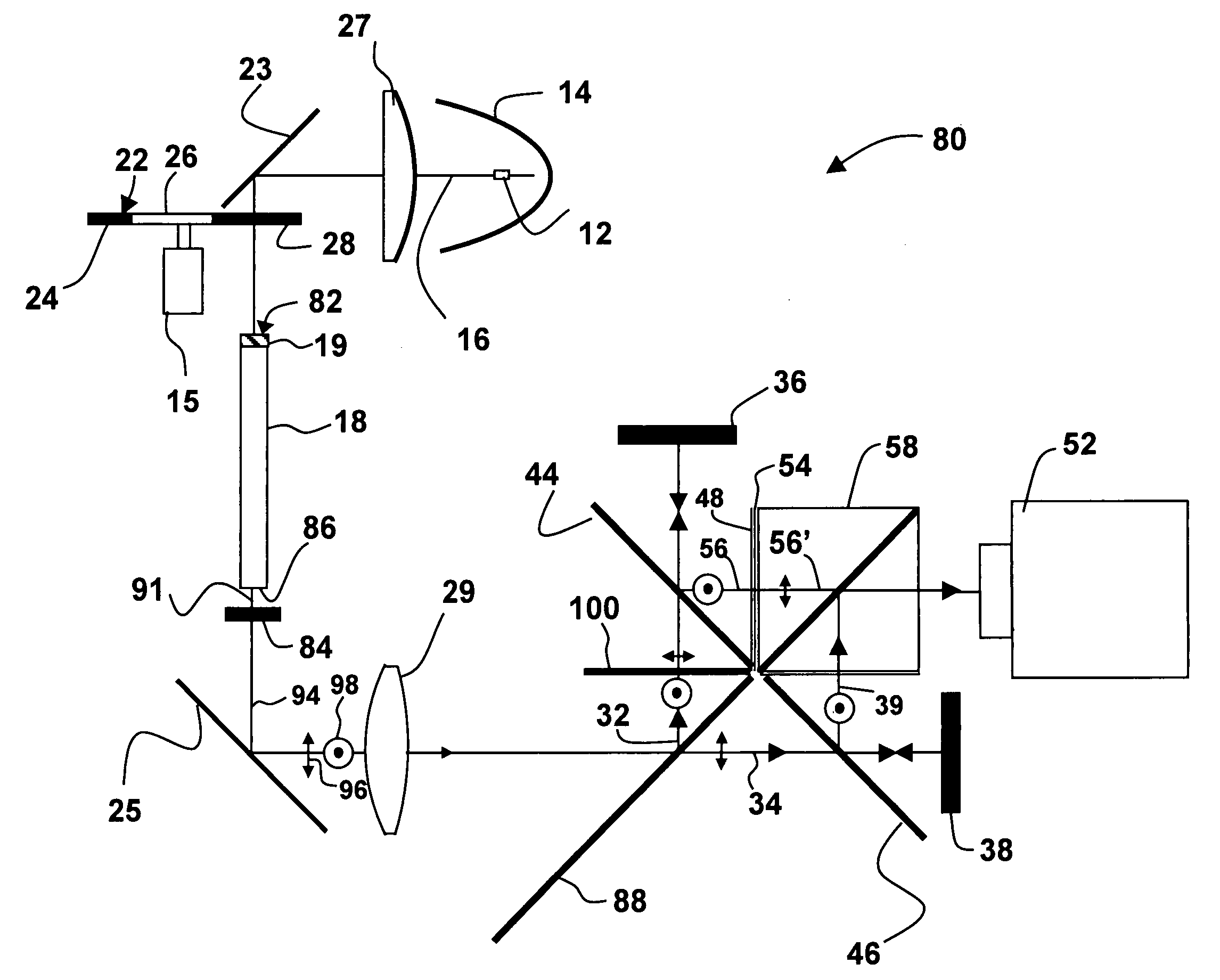
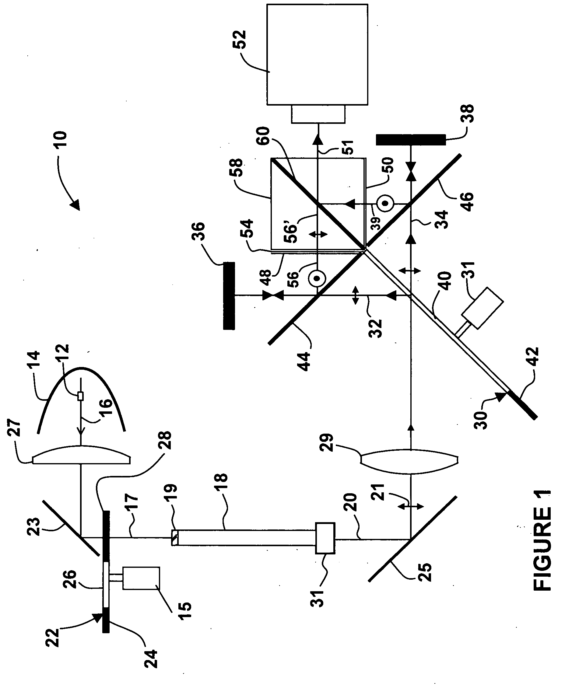
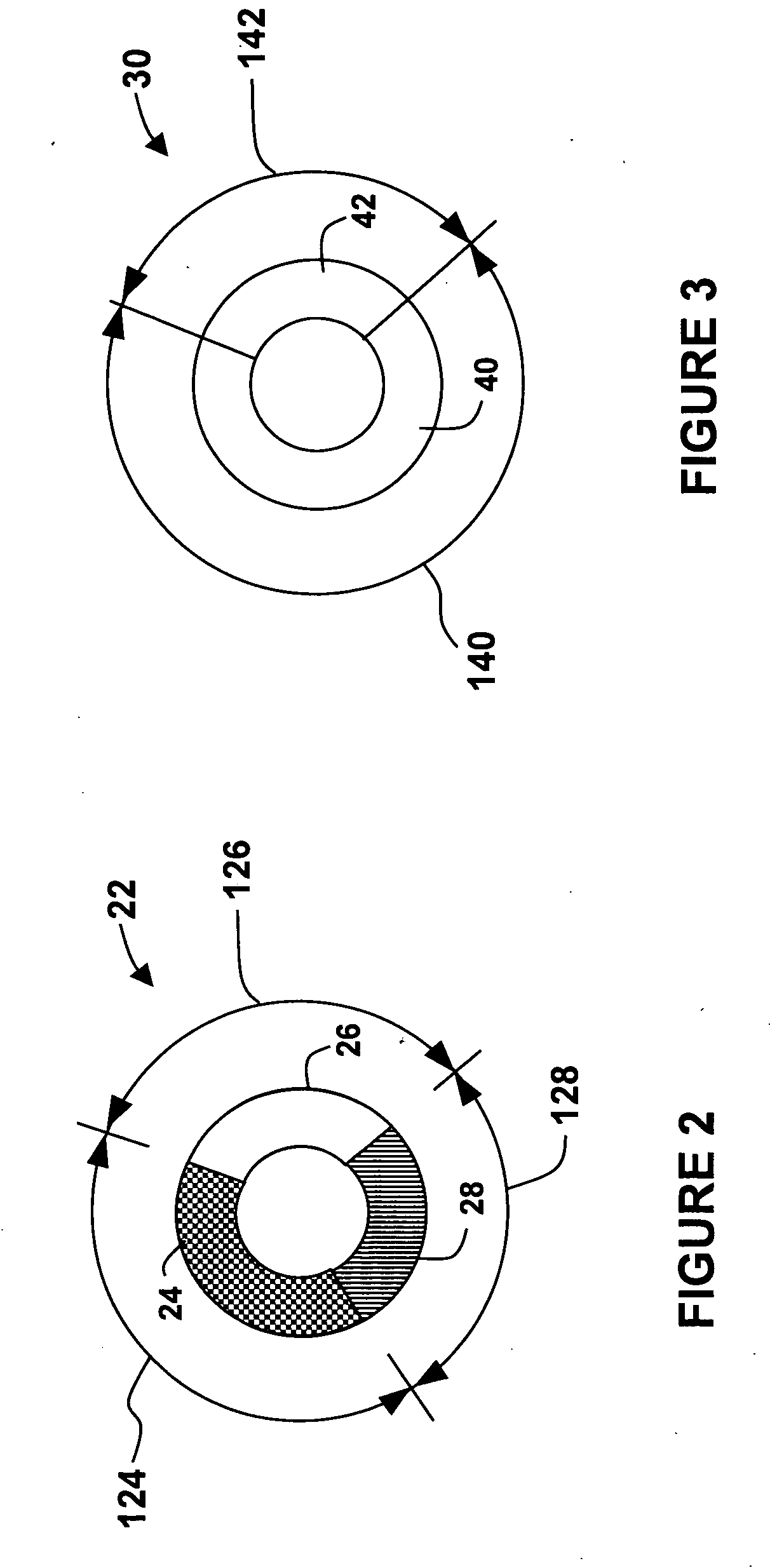
[0038] Brightness in the systems described above is also limited by the requirement that the overall system be “white-point balanced.” White-point balanced refers to the need to limit the maximum brightness of two of the displayed color channels in proper relation to the third, which is referred to as the “brightness-limiting color channel,” in order that the white state, i.e. when all color channels are turned up to maximum balanced brightness, of the system match some specified color temperature corresponding to the color of a blackbody radiator of a given temperature, typically between 6,000° K and 12,000° K. In the BCDCS-type two-panel system described above, color assignments to the fixed-color and two-color panels can be made arbitrarily. However, to achieve a maximally bright color-balanced system, the color channel that would limit the overall white-balanced brightness of a three-panel system should be assigned to the non-color-sequencing imager, i.e. the fixed color panel. ...


PUM


Abstract

A lamp in a color management system provides light to a color wheel having color filter segments that transmit light having a secondary color, namely cyan, magenta, and yellow. A light integrator with a polarizing element, such as a polarization converter or polarizing filter, provides a beam of the secondary color. A primary color separator, such as second color wheel, transflective dichroic beamsplitter, or color-sensitive polarizing switch in combination with an input polarizing beamsplitter, separates the secondary color beam into a first polarized primary color beam and a second polarized primary color beam, which are directed to first and second imager panels. A beam combiner combines the first polarized primary color beam from the first imager and the second polarized primary color beam from the second imager to form a projection beam.

Description

CROSS-REFERENCE TO RELATED APPLICATIONS [0001] The present invention claims priority from U.S. Patent Application No. 60 / 573,070 filed May 21, 2004, which is incorporated herein by reference.TECHNICAL FIELD [0002] The present invention relates to a color projection display system, and in particularly to a color display system using multiple imager panels. BACKGROUND OF THE INVENTION [0003] Projection display systems based on liquid-crystal-on-silicon (“LCoS”) microdisplay technology commonly employ one, two, or three LCoS imaging panels in order to create a full color projected image. When three panels are used, each panel is illuminated with one of the three primary colors. Each panel is electronically addressed with video data corresponding to the color channel for the illuminating light received at that imager. Finally these three monochrome images are projected onto the screen simultaneously, resulting in a high brightness image that has no artifacts associated with temporal col...

Claims


Application Information

Patent Timeline
IPC IPC(8): G02F1/133G02F1/13G03B21/00G03B21/14G03B21/20H04N9/31
CPCG02B26/008G02B27/1026G02B27/141G02B27/283G03B21/2026H04N9/3117H04N9/3197G03B21/2073H04N9/3111
Inventor GREENBERG, MICHAEL R.MCGETTIGAN, ANTHONY D.
Owner JDS UNIPHASE CORP
Why Eureka
Try Eureka