Tristate electrochromic device

a technology of electrochromic devices and tristates, applied in non-linear optics, instruments, optics, etc., can solve the problems of prior art devices being limited in a number of applications, unable to enable users to selectively absorb light in the visible or near-infrared region, etc., and achieve the effect of sufficient stability

Active Publication Date: 2005-11-24
GENTEX CORP
View PDF27 Cites 27 Cited by
  • Summary
  • Abstract
  • Description
  • Claims
  • Application Information

AI Technical Summary

Benefits of technology

[0014] In accordance with the present invention, an electrochromic device is provided which is capable of operating between a first state, a second state, and a third state, comprising: (a) a first substantially transparent substrate having an electrically conductive material associated therewith; (b) a second substrate having an electrically conductive material associated therewith; (c) an electrochromic medium contained within a chamber positioned between the first and second substrates which comprises: (1) at least one solvent; (2) a first cathodic material; (3) a first anodic material; (4) a second anodic material, wherein both of the anodic and cathodic materials are electroactive and at least one of the anodic and cathodic materials is electrochromic; (d) wherein the cathodic material is present “in excess” such that the current is limited by the first anodic material when the device reaches the high potential range of the second state and while operating in the second state only

Problems solved by technology

While the above-identified references disclose utilizing a plurality of anodic and/or cathodic materials in the medium of an electrochromic device, to the best of Applicant's knowledge, they do not enable a user to

Method used


Image

  • Tristate electrochromic device
  • Tristate electrochromic device
  • Tristate electrochromic device

Examples


Embodiment Construction

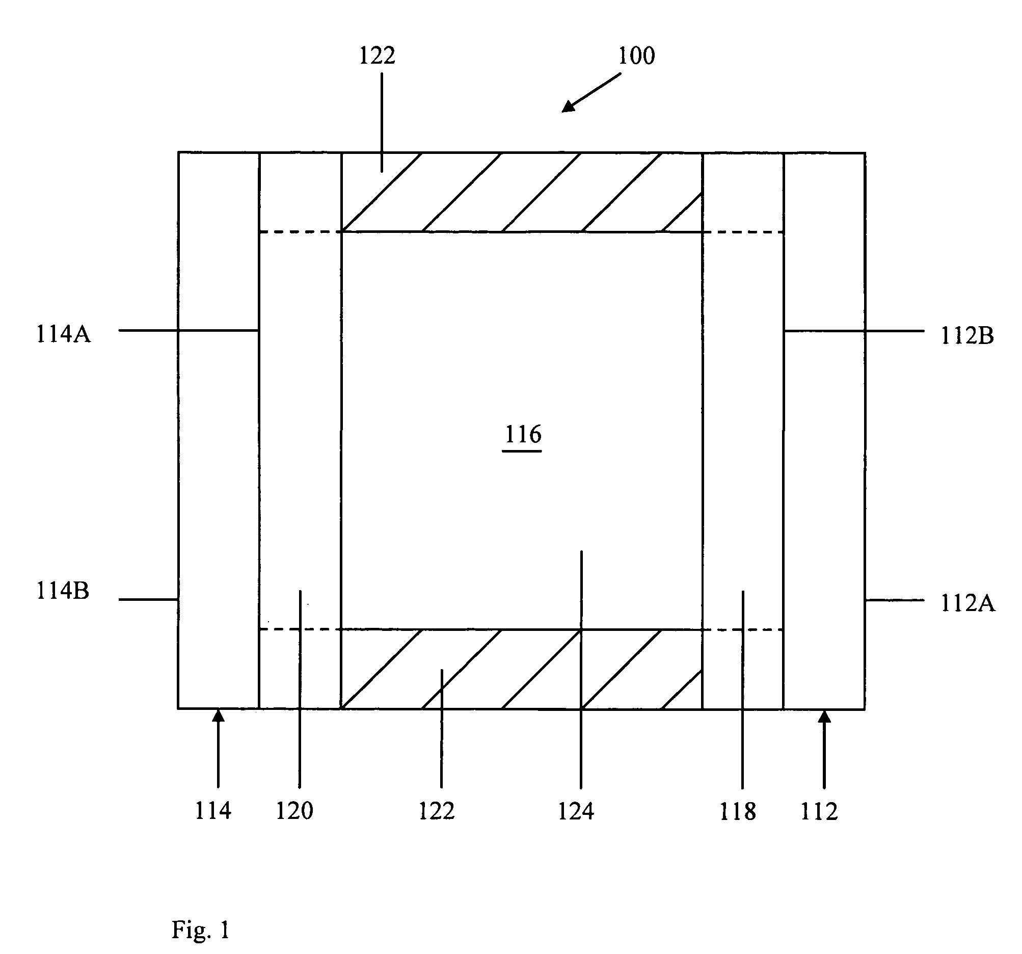
[0019] Referring now to the drawings and to FIG. 1 in particular, a cross-sectional schematic representation of tristate electrochromic device 100 is shown, which generally comprises first substrate 112 having front surface 112A and rear surface 112B, second substrate 114 having front surface 114A and rear surface 114B, and chamber 116 for containing electrochromic medium 124. It will be understood that tristate electrochromic device 100 may comprise, for illustrative purposes only, a window, a mirror, a display device, and the like. It will be further understood that FIG. 1 is merely a schematic representation of tristate electrochromic device 100. As such, some of the components have been distorted from their actual scale for pictorial clarity. Indeed, numerous other electrochromic device configurations are contemplated for use, including those disclosed in U.S. Pat. No. 5,818,625 entitled “Electrochromic Rearview Mirror Incorporating A Third Surface Metal Reflector,” and U.S. Pat...


PUM


Abstract

An electrochromic medium for use in a tristate electrochromic device, comprising: (a) at least one solvent; (b) at least one anodic material; (c) at least one cathodic material, wherein both of the anodic and cathodic materials are electroactive and at least one of the anodic and cathodic materials is electrochromic; (d) wherein, in a first state, the electrochromic medium exhibits a maximum light transmission; (e) wherein, in a second state, variable attenuation occurs to a significant extent in one of visible radiation or near-infrared radiation without significant attenuation in the other; and (f) wherein, in a third state, variable attenuation occurs to a significant extent in the other spectral region.

Description

CROSS-REFERENCE TO RELATED APPLICATIONS [0001] This application is a continuation of U.S. application Ser. No. 10 / 850,989, filed on May 21, 2004, now U.S. Pat. No. 6,876,479, which is hereby incorporated herein by reference in its entirety.BACKGROUND OF THE INVENTION [0002] 1. Field of the Invention [0003] The present invention relates in general to electrochromic devices and, more particularly, to a tristate electrochromic device having anodic and / or cathodic materials which, upon application of different applied potentials, can selectively absorb predetermined wavelengths of electromagnetic radiation, including visible radiation (i.e. visible light ranging in wavelength from approximately 400 nanometers (nm) to approximately 750 nm) and / or near-infrared radiation (i.e. heat ranging in wavelength from approximately 750 nm to approximately 2,400 nm) and vice versa—depending upon the device configuration. [0004] 2. Background Art [0005] Electrochromic devices have been known in the a...

Claims


Application Information

Patent Timeline
IPC IPC(8): G02F1/1503G02F1/153G02F1/163
CPCG02F1/1521G02F2203/11G02F1/163G02F1/153G02F1/1503
Inventor GIRI, PUNAMGUARR, THOMAS F.
Owner GENTEX CORP
Why Eureka
Try Eureka