Method for making a perpendicular magnetic recording write head with a self aligned stitched write shield

a writing shield and perpendicular magnetic recording technology, applied in the direction of writing heads with metal sheet cores, record information storage, instruments, etc., can solve the problems of super-paramagnetic limit of magnetic media, write head illustrated will create problems of unwanted side writing

Inactive Publication Date: 2005-11-24
HEADWAY TECH INC
View PDF14 Cites 23 Cited by
  • Summary
  • Abstract
  • Description
  • Claims
  • Application Information

AI Technical Summary

Benefits of technology

[0022] As can be seen from the shape of the graphs, the stitched pole produces maximum field gradients.

Problems solved by technology

At this ultra-high area density, the super-paramagnetic limit of magnetic media becomes a problem, which is the condition wherein magnetic domains are so small that they lack thermal stability and can be randomly aligned by thermal agitation.
Batra et al. note that the write head illustrated will create problems of unwanted side writing because of the lack of a shielding mechanism to contain the field laterally and prevent the field from spreading beyond the track being written upon.

Method used


Image

  • Method for making a perpendicular magnetic recording write head with a self aligned stitched write shield
  • Method for making a perpendicular magnetic recording write head with a self aligned stitched write shield
  • Method for making a perpendicular magnetic recording write head with a self aligned stitched write shield

Examples


first preferred embodiment

[0026] The present invention, in a first preferred embodiment, is a method of fabricating a double coil perpendicular magnetic write head having a stitched write shield formed between a write gap layer and a main write shield. The fabrication consists of an upper and a lower portion, the lower portion containing a lower conducting coil layer which is finally connected to an upper coil layer in the upper portion. The upper portion, which is formed on the lower portion, contains the main pole as its lowest layer, an upper coil layer formed over the main pole, and a yoke which overarches the upper coil, and connects a rear portion of the main pole to a main write shield in the ABS plane.

[0027] Referring first to FIG. 4a, there is shown a substrate (10) for the fabrication, which is typically a shield layer that may serve as a bottom shield for the write head of the present invention and / or as an upper shield for a read head that may be positioned beneath the write head. The read head ...

second preferred embodiment

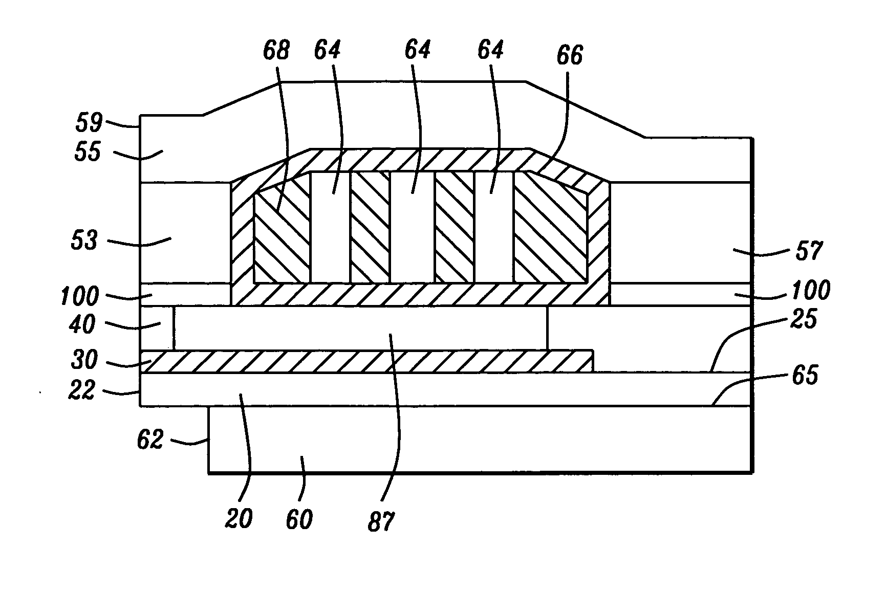
[0037] The present invention, in a second preferred embodiment, is a method of fabricating a single coil perpendicular magnetic write head having a stitched write shield formed between a write gap layer and a main write shield. The formation of this embodiment follows exactly the steps in the formation of the upper portion of the first preferred embodiment, wherein all the steps in the formation of the lower portion of the write head are omitted. The fabrication process can be understood by referring to FIG. 2b, which shows the completed invention, and to the steps disclosed in discussing FIGS. 4c-4f, which shows the steps involved in completing the upper portion of the first embodiment. In short, the second embodiment begins with the formation of a bottom yoke layer ((60) in FIGS. 2b and 4b) and proceeds from that point in a manner identical to the formation of the second portion of the write head in the first embodiment. The following discussion will be briefer than the discussion...


PUM

PropertyMeasurementUnit
thicknessaaaaaaaaaa
thicknessaaaaaaaaaa
heightaaaaaaaaaa

Abstract

A perpendicular magnetic recording (PMR) head with single or double coil layers has a small write shield stitched onto a main write shield. The stitched shield allows the main write pole to produce a vertical write field with sharp vertical gradients that is reduced on both sides of the write pole so that adjacent track erasures are eliminated. From a fabrication point of view, both the main pole and the stitched shield are defined and formed using a single photolithographic process, a trim mask and CMP lapping process so that the main shield can be stitched onto a self-aligned main pole and stitched shield.

Description

RELATED APPLICATION [0001] This Application is related to Docket No. HT 03-015, Ser. No. 10 / 814,077 Filing date Mar. 31, 2004, assigned to the same assignee as the present ApplicationBACKGROUND OF THE INVENTION [0002] 1. Field of the Invention [0003] This invention relates generally to the design of magnetic recording heads for high recording density, particularly heads designed for perpendicular magnetic recording [0004] 2. Description of the Related Art [0005] The commonly used inductive magnetic write head technology utilizes the longitudinal configuration. In this configuration a magnetic field fringes across a write gap between an upper and a lower pole in the plane of the air bearing surface (ABS) of the write head. This plane will be referred to as the longitudinal plane. The ABS is positioned above and parallel to the surface of a recording medium, such as a hard disk. The surface of the hard disk is formed of a magnetic medium. As the hard disk moves beneath the ABS, a hori...

Claims


Application Information

Patent Timeline
Patent Type & Authority Applications(United States)
IPC IPC(8): G11B5/127G11B5/147G11B5/31
CPCG11B5/1278G11B5/3116G11B5/3143G11B5/3163Y10T29/4906Y10T29/49062Y10T29/49041Y10T29/49044Y10T29/49048
Inventor HAN, CHERNG-CHYITAKANO, KENICHI
Owner HEADWAY TECH INC
Why Eureka
Try Eureka