Lighted sign fixture having reflective surface

a technology of reflective surface and lighted sign, which is applied in the direction of lighting support devices, instruments, lighting and heating apparatuses, etc., can solve the problems of burden on manufacturability and cost, and the nature of structural components impede the maintenance and repair of such lighting fixtures

Inactive Publication Date: 2005-11-24
JUNG HAE RYONG
View PDF19 Cites 4 Cited by
  • Summary
  • Abstract
  • Description
  • Claims
  • Application Information

AI Technical Summary

Benefits of technology

[0008] It is, therefore, an object of the present invention to provide a lighting system capable of generating a brightly, visually crisp and highly contrasting visible emission of light through a sign member.

Problems solved by technology

The need to pre-form and / or pre-assemble the reflective surface contour in each of these cases not only burdens manufacturability and cost, but the fixed nature of the structural components impedes the ready maintenance and repair of such lighting fixture.

Method used


Image

  • Lighted sign fixture having reflective surface
  • Lighted sign fixture having reflective surface
  • Lighted sign fixture having reflective surface

Examples


Embodiment Construction

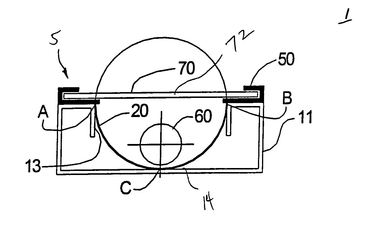
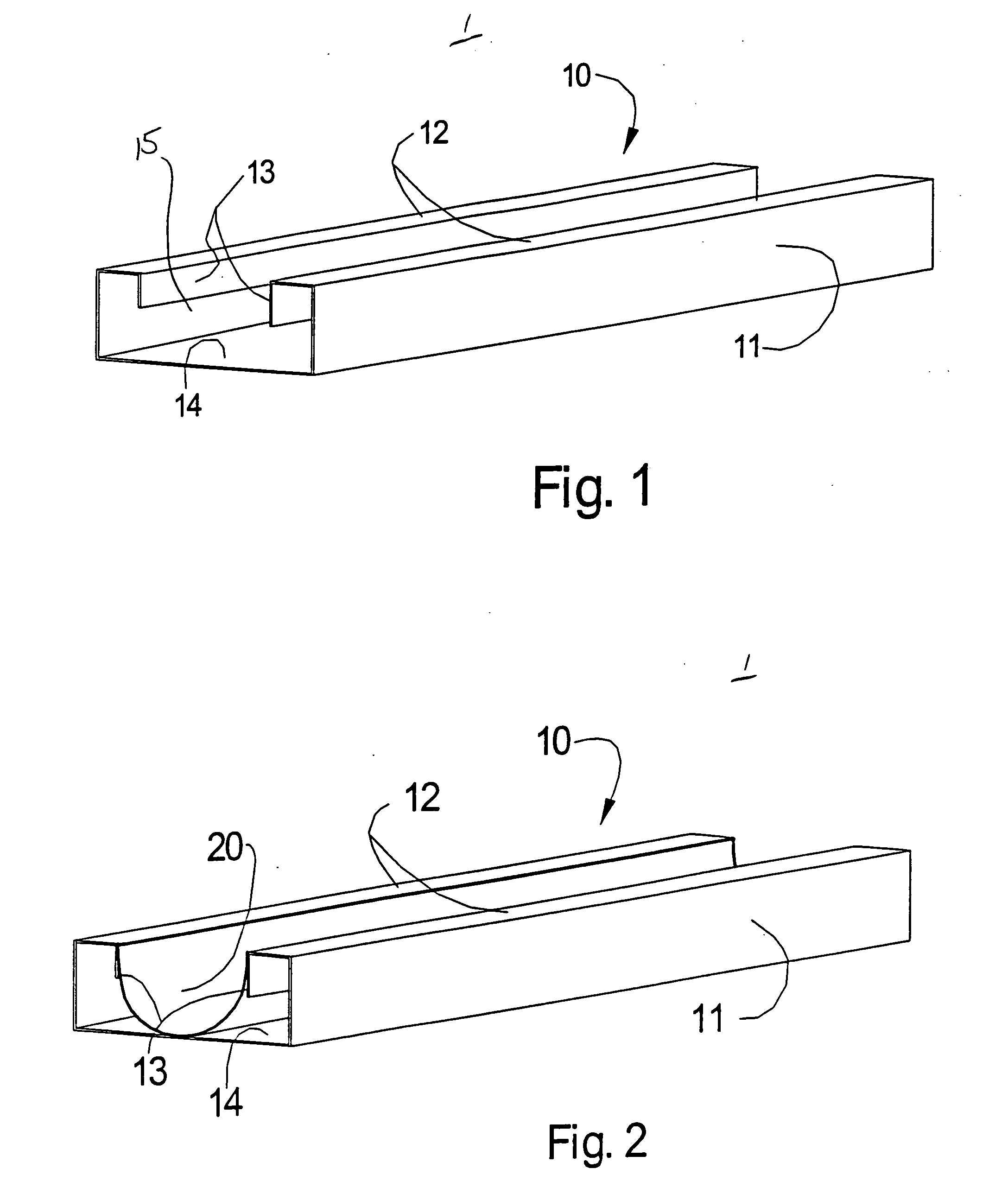
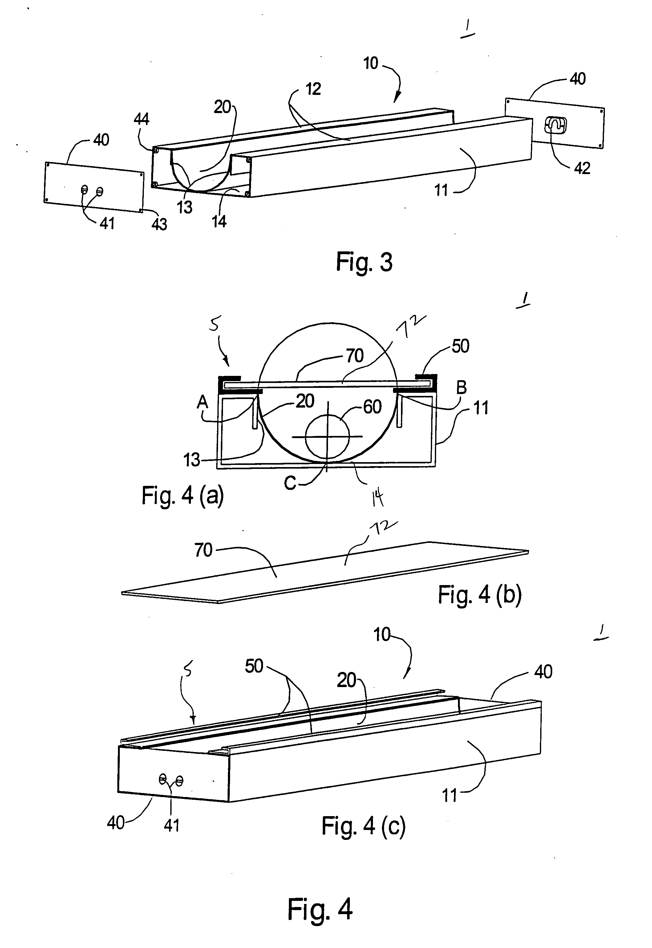
[0017] Referring now to FIGS. 1-4(c), there is illustrated a lighting system 1 formed in accordance with an exemplary embodiment of the present invention. In this exemplary embodiment, lighting system 1 generally includes a fixture body assembly 10 and a face assembly 5 (shown in FIG. 4a) coupled thereto. Fixture body and face assemblies 10, 5 together house a light source 60 and retain a flexible reflective member 20 at a predetermined arcuate configuration thereabout. In accordance with one aspect of the present invention, flexible reflective member 20 need not itself be pre-shaped or otherwise pre-configured with the predetermined curvature in its reflective surface contour necessary for generating the desired illumination effect. Flexible reflective member 20 need only be of sufficient flexibility to form the necessary curvature when it is slid or otherwise inserted within fixture body assembly 10.

[0018] The retaining structure defined by fixture body assembly 10, preferably in...


PUM

PropertyMeasurementUnit
thicknessaaaaaaaaaa
thicknessaaaaaaaaaa
diameteraaaaaaaaaa

Abstract

The subject lighting system (1) generally comprises a fixture body assembly (10); a face assembly (5) coupled to the fixture body assembly (10) to extend at least partially over a channel (15) defined thereby; a flexible reflective member (20) disposed in the channel (15) formed by the fixture body assembly (10) to define a reflective surface; and, a light source (60) disposed adjacent a base portion of the reflective surface. The fixture body assembly (10) includes a longitudinally extended inside base surface (14) and at least a pair of laterally opposed inner side surfaces (13) transversely oriented relative to the inside base surface (14), such that the inner side and inside base surfaces define the longitudinally extended channel (15). The face assembly (5) extends at least partially over the channel (15), and includes a light transmissive portion (72). The reflective member (20) is defectively retained by the face and fixture body assemblies (5, 10) to define a reflective surface concavely arcuate in sectional contour, with the base portion of its reflective surface being supported by the fixture body assembly's inside base surface (14). The light emitted by the light source (60) in this system (1) is directed in a substantially wide angle illumination pattern through the light transmissive portion (72) of the face assembly (5).

Description

RELATED U.S. APPLICATION DATA [0001] This Application is based on U.S. Provisional Patent Application, Ser. No. 60 / 542,877, filed on 10 Feb. 2004.BACKGROUND OF THE INVENTION [0002] 1. Field of the Invention [0003] The subject lighted sign fixture having reflective surface is generally directed to a lighting system capable of visually presenting a bright, visually crisp, and contrasting wide angle illumination pattern through a light transmissive portion of a given sign. More specifically, the lighted sign fixture is one whose simple structure permits easy and convenient fabrication while maintaining a quadratic curvature in its reflective surface. The lighted sign for the fixture provides a simple retentive structure for maintaining a flexible reflective member in this manner. [0004] 2. Prior Art [0005] Lamp lighting systems are known in the art, as are lighted sign fixtures having reflective surfaces. One such lighting system is disclosed in U.S. Pat. No. 5,509,223, issued Apr. 23,...

Claims


Application Information

Patent Timeline
Patent Type & Authority Applications(United States)
IPC IPC(8): F21S4/00F21S8/00F21V7/00F21V7/22F21V15/01F21V15/015G09F13/14
CPCF21V7/005F21V7/22G09F13/14F21V15/015F21Y2103/00F21V15/01F21V7/24F21V7/28
Inventor JUNG, HAE-RYONG
Owner JUNG HAE RYONG
Why Eureka
Try Eureka