
Tray drive

a technology of rotating platters and rotating plates, applied in the field of rotating platters, can solve the problems of increasing increasing the cost of parts, increasing the number of manufacturing steps, etc., and achieving the effect of reducing the weight of the load and preventing the rapid change of the movement speed of the rotating pla

Inactive Publication Date: 2005-11-24
FUNAI ELECTRIC CO LTD
View PDF12 Cites 13 Cited by
  • Summary
  • Abstract
  • Description
  • Claims
  • Application Information

AI Technical Summary

Benefits of technology

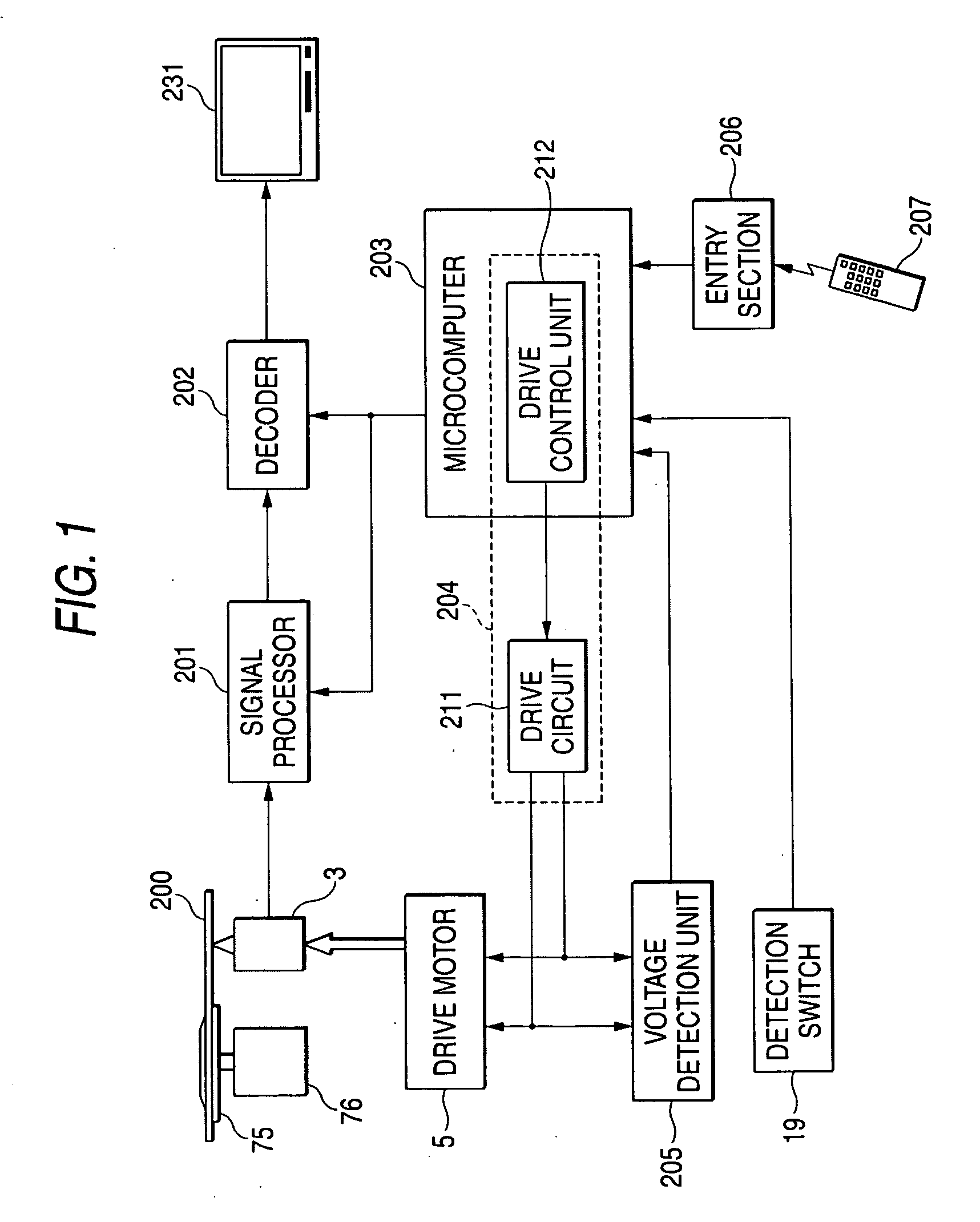
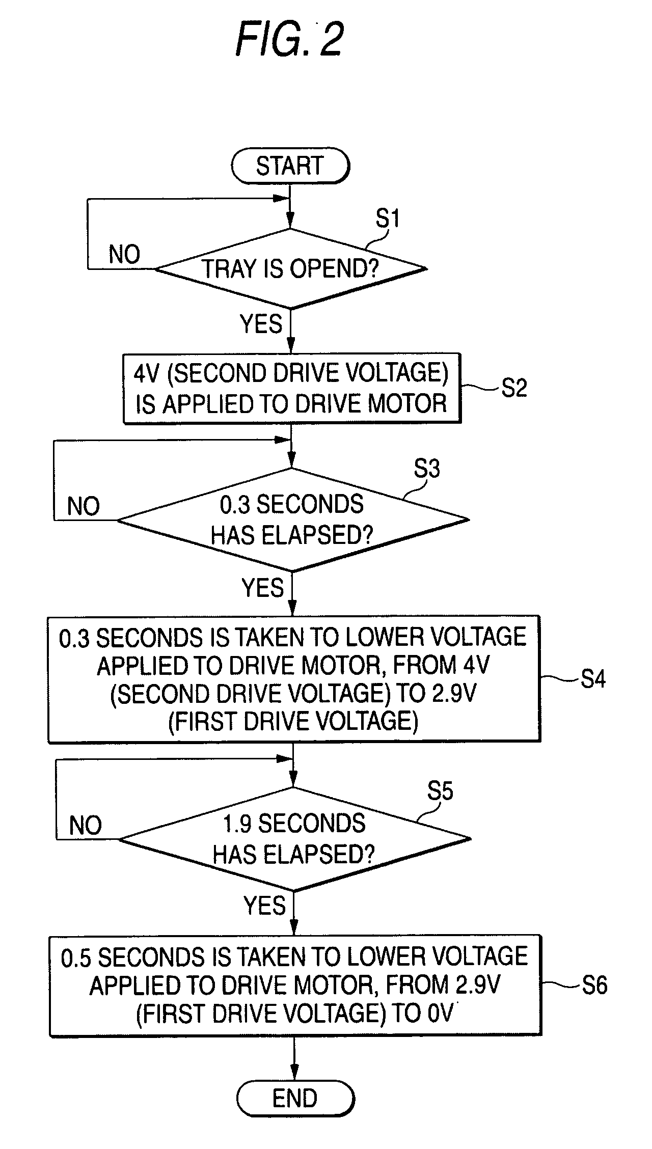
The invention provides a tray drive that can smoothly move a tray between an ejected position and a retracted position without causing any jolts or impacts. This is achieved by gradually lowering the voltage applied to the drive motor and using a high voltage during the initial period of the drive to provide sufficient force to move the tray. Additionally, the invention includes a mechanism for detecting the position of the tray and a mechanism for gradually lowering the voltage applied to the drive motor to prevent any impact or change in movement speed. Overall, the invention improves the stability and smoothness of the tray drive.

Problems solved by technology

However, the provision of the two switches: the limit switch for detecting the movement to the ejected position and the limit switch for detecting the movement to the retracted position, involves an increase in the number of parts, an increase in the cost of parts, and an increase in the number of manufacturing steps.
Besides, the provision of the switch for detecting the direction of movement of the disk tray complicates the configuration of the switch, thus involving an increase in cost that is equivalent to or greater than the increase in the cost of parts which is involved when the two limit switches are provided.
However, in the case of using the first related art, there arises the problem shown below.
Consequently, the configuration becomes more complicated than that of providing the two limit switches, thus involving a significant increase in the cost of parts.
Besides, in the case of using the second related art, a current detection circuit (voltage detection circuit) for detecting a current of the drive motor is required, and an OP amplifier is indispensable to the current detection circuit (voltage detection circuit), thus involving an increase in the cost of parts.

Method used


Image

  • Tray drive
  • Tray drive
  • Tray drive

Examples


Embodiment Construction

[0034] An embodiment of the invention will hereinafter be described with reference to the drawings.

[0035]FIG. 5 shows the exterior of a disk device provided with an embodiment of a tray drive according to the invention.

[0036] A disk device 100 is a device into the inside of which is loaded a disk, such as a DVD, placed on a tray 2, wherein the disk loaded is irradiated with a laser beam to record / reproduce a signal. Loading / unloading of the disk is performed as the tray 2 having the disk placed thereon is reciprocally moved by a tray drive mechanism between a retracted position and an ejected position (the direction of which movement is shown by arrow A). The movement of the tray 2 to the retracted position is detected by a tray position detection unit (which is described in detail later), but a unit for detecting the movement of the tray 2 to the ejected position is omitted.

[0037]FIG. 6 shows the tray drive mechanism in an initial state (power-off state). That is, a tray drive m...


PUM

PropertyMeasurementUnit
drive voltageaaaaaaaaaa
voltageaaaaaaaaaa
voltageaaaaaaaaaa

Abstract

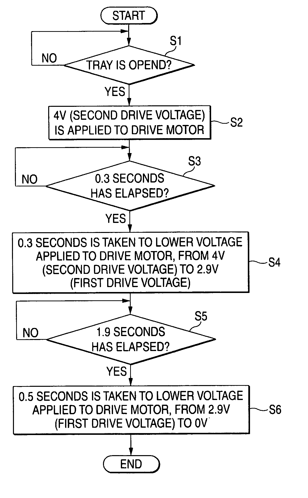
In the configuration including: a tray drive mechanism for reciprocally moving a tray with a drive motor as a power source; and a motor drive unit for driving the drive motor, after the movement of the tray in a retracted position is started by applying a first drive voltage to the drive motor, when a predetermined time duration elapses after the time at which the tray is deemed to have moved to the ejected position, the motor drive unit gradually lowers a voltage applied to the drive motor, from the first voltage toward 0V.

Description

BACKGROUND OF THE INVENTION [0001] 1. Field of the Invention [0002] The present invention relates to a tray drive for reciprocally moving a tray having a disk placed thereon between an ejected position and a retracted position and, more particularly, to a tray drive having omitted therefrom a switch for detecting that the tray has moved to the ejected position. [0003] 2. Description of the Related Art [0004] A DVD player is provided with a tray for placing a DVD thereon. To replace the DVD, this tray is moved toward the ejected position by a drive motor until a limit switch detects that the tray has moved to the ejected position. Besides, to reproduce the DVD placed on the tray, the tray is moved toward the retracted position by the drive motor until a limit switch detects that the tray has moved to the retracted position (e.g., see JP-A-2000-285561 and JP-A-2001-243687). Besides, a switch for detecting the direction of movement of the tray is provided, and the movement of the tray ...

Claims


Application Information

Patent Timeline
Patent Type & Authority Applications(United States)
IPC IPC(8): G11B17/056G11B17/04
CPCG11B17/056
Inventor SAKAGAMI, KATSUYA
Owner FUNAI ELECTRIC CO LTD
Learn More