Linear compressor with sensor

a sensor and compressor technology, applied in the direction of positive displacement liquid engine, piston pump, pump parameter, etc., can solve the problems of increasing manufacturing costs, increasing assembly time, and sensor core b>120/b> not being easily fixed to the desired position of the core support member, so as to improve productivity and reduce manufacturing costs

Inactive Publication Date: 2005-11-24
SAMSUNG GWANGJU ELECTRONICS CO LTD
View PDF5 Cites 19 Cited by
  • Summary
  • Abstract
  • Description
  • Claims
  • Application Information

AI Technical Summary

Benefits of technology

[0018] Therefore, it is an aspect of the invention to provide a linear compressor wherein a sensor core is engaged with a core-supporting member in such a manner that the height of the sensor core can be adjusted without using washers for adjusting the height of the sensor, whereby productivity is improved and manufacturing costs are reduced.
[0019] It is another aspect of the invention to provide a linear compressor wherein the sensor core is not forcibly fitted on the core-supporting member but securely fitted on the core-supporting member through the screw engagement of the sensor core and the core-supporting member, whereby deformation of the core-supporting member is prevented, and the core-supporting member is fixed at a desired position.
[0024] The sensor core is provided with an engagement groove so that the sensor core can be easily rotated by means of a tool inserted in the engagement groove.
[0026] The sensor core is provided with a stopper wall for preventing the sensor core from being fitted on the core-supporting member above a prescribed distance.

Problems solved by technology

As a result, the assembly time is increased, and addition of the washers 135 may be necessary, which leads to increase of the manufacturing costs.
Furthermore, the sensor core 120 may not be easily fixed to a desired position of the core-supporting member 121.

Method used


Image

  • Linear compressor with sensor
  • Linear compressor with sensor
  • Linear compressor with sensor

Examples


Embodiment Construction

[0035] Reference will now be made in detail to the embodiment of the present invention, an example of which is illustrated in the accompanying drawings. The embodiment is described below to explain the present invention by referring to the figures.

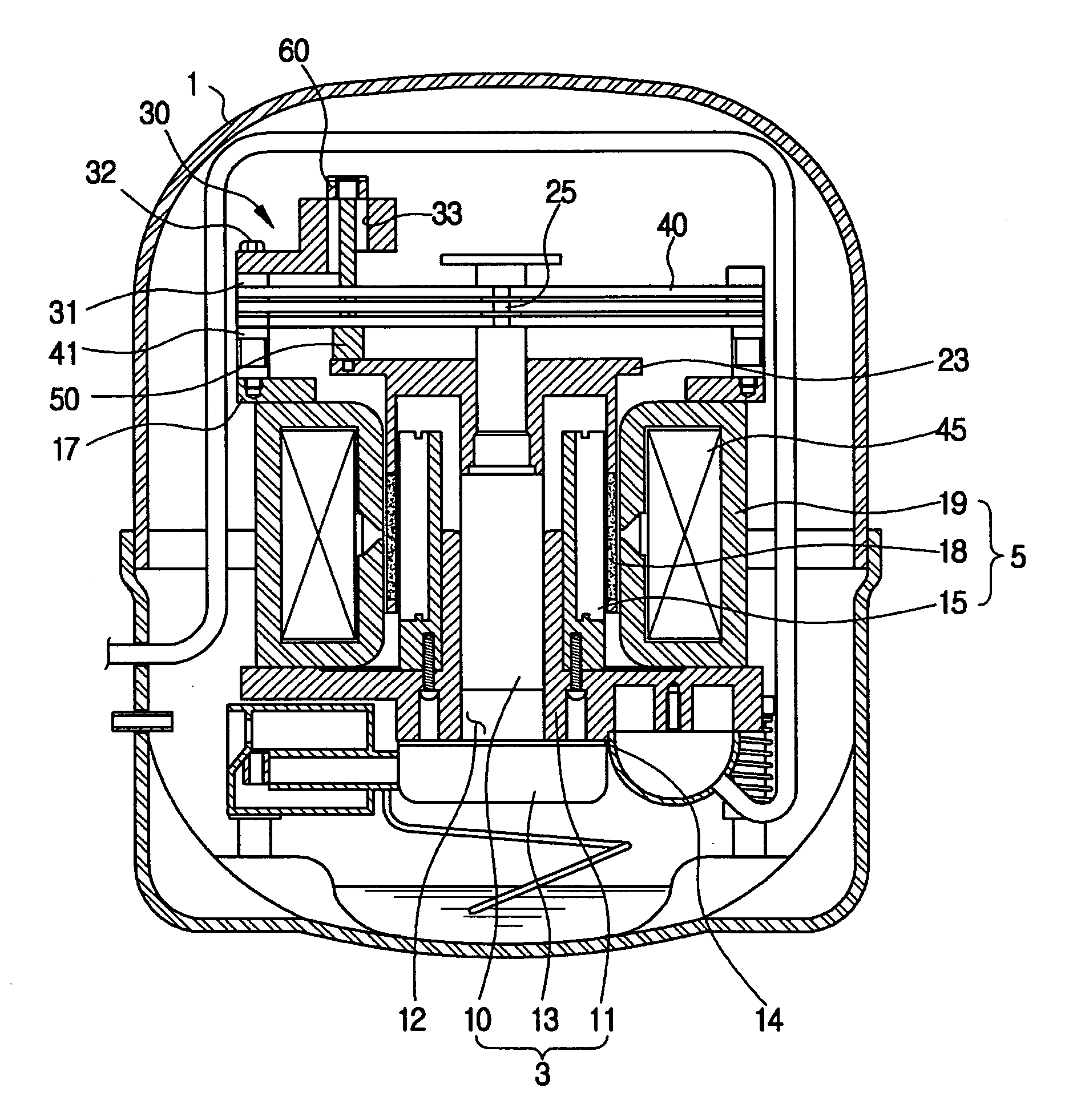
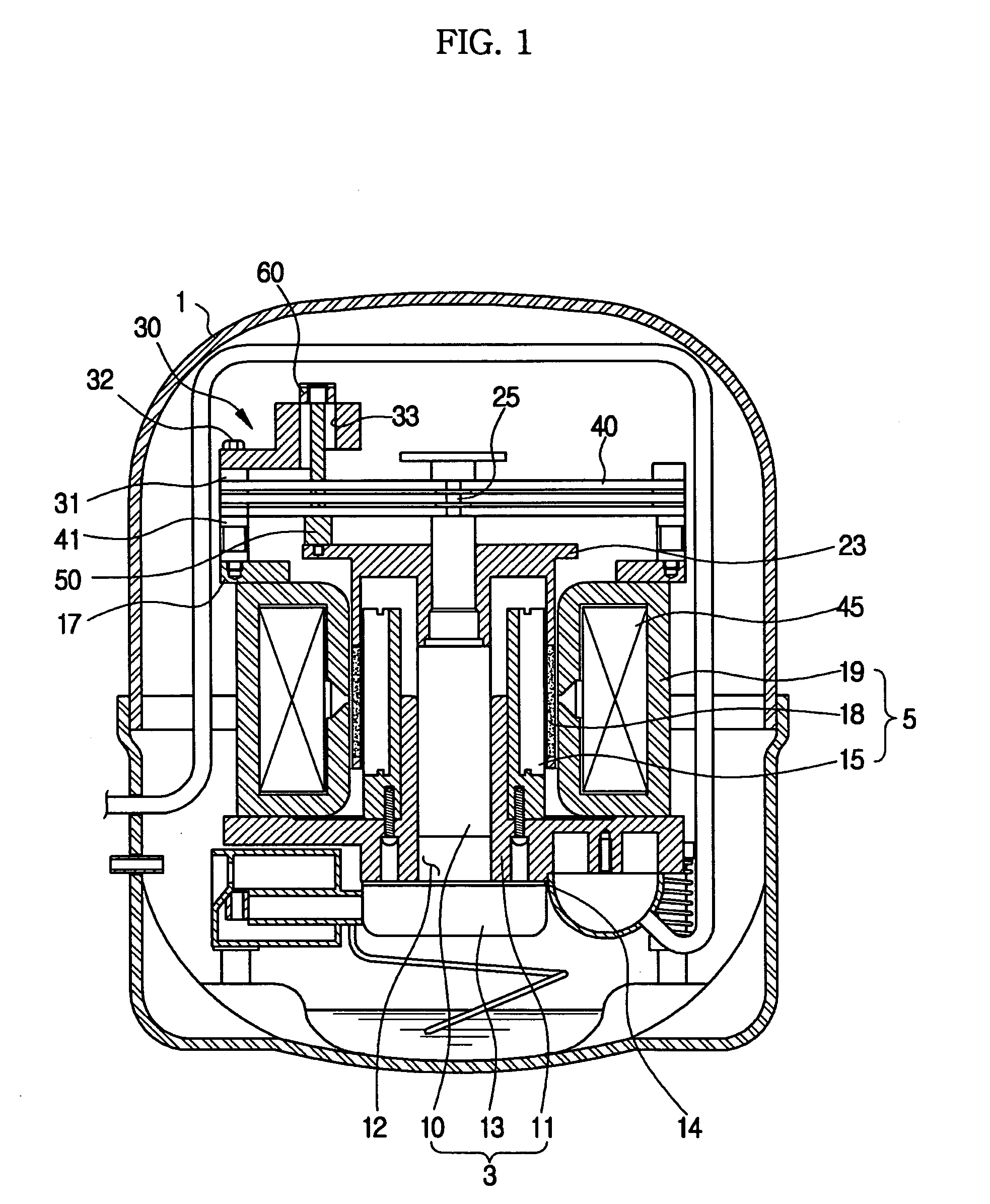
[0036]FIG. 1 is a sectional view showing a linear compressor according to the present invention. As shown in FIG. 1, the linear compressor comprises a hermetically sealed container 1, a compressing unit 3 for compressing a coolant, and a driving unit 5 for generating power.

[0037] The compressing unit 3 includes a cylinder block 11 forming a compression chamber 12, a piston 10 disposed in the compression chamber 12 such that the piston 110 can be reciprocated in the compression chamber 12, and a cylinder head 13 provided at the lower part of the cylinder block 11. The cylinder head 13 has a coolant-introducing chamber (not shown) and a coolant-discharging chamber (not shown) defined therein. Between the cylinder block 11 and the cylinder ...


PUM


Abstract

Disclosed herein is a linear compressor having a sensor for detecting the position of a piston. The linear compressor has a position-detecting unit for detecting the position of a piston. The position-detecting unit comprises a sensor core mounted such that the sensor core can be moved along with the piston and the position of the sensor core can be adjusted, and a sensor having a detection hole formed therein for detecting the position of the sensor core disposed in the detection hole. The sensor is fixed to a fixing frame. The sensor core is engaged with a core-supporting member in such a manner that the height of the sensor core can be adjusted without using washers for adjusting the height of the sensor, whereby productivity is improved and manufacturing costs are reduced.

Description

CROSS-REFERENCE TO RELATED APPLICATION [0001] This application claims the benefit of Korean Patent Application No. 2004-36266, filed on May 21, 2004 in the Korean Intellectual Property Office, the disclosure of which is incorporated herein by reference. BACKGROUND OF THE INVENTION [0002] 1. Field of the Invention [0003] The present invention relates to a linear compressor, and, more particularly, to a linear compressor having a sensor for detecting the position of a piston. [0004] 2. Description of the Related Art [0005] Generally, a compressor is part of a refrigerating cycle that is used to generate conditioned air through the circulation of a coolant in an air conditioner or a refrigerator. Specifically, the compressor serves to compress the coolant at high temperature and high pressure. One kind of compressor is a linear compressor, which has a linear motor driven through the interaction due to change in direction of magnetic flux for reciprocating a piston. [0006]FIG. 6 is a se...

Claims


Application Information

Patent Timeline
Patent Type & Authority Applications(United States)
IPC IPC(8): F04B17/04F04B17/00F04B35/04F04B49/06F04B49/12
CPCF04B35/045F04B49/06F04B2201/0201F05B2210/12F05B2210/14F05B2260/301F16B5/02H02K33/16Y10S417/902
Inventor PARK, JONG REA
Owner SAMSUNG GWANGJU ELECTRONICS CO LTD
Why Eureka
Try Eureka