Transmission diversity with two cross-polarised antennas arrays

Inactive Publication Date: 2005-11-24
NOKIA SOLUTIONS & NETWORKS OY
View PDF7 Cites 34 Cited by
  • Summary
  • Abstract
  • Description
  • Claims
  • Application Information

AI Technical Summary

Benefits of technology

[0033] Consequently, it is an object of the present invention to provide an improved method for selecting a diversity mode to be applied by a transmitter h

Problems solved by technology

Generally, the mode selection problem resides in finding measures and a method by which a best suitable mode can be selected for each link.
The mode selection problem is linked to the employed antenna solution at the transmitter.
If feedback delay is large when compared to channel coherence time, then system performance is corrupted.
Similarly, if transmit antennas correlate heavily, then both antennas are in good and bad states simultaneously and the lack of diversity corrupts the system performance.
However, if P1/P2 is all the time very high—or very low—then the same antenna provides better channel almost all the time and feedback delay or antenna correlation are not corrupting the system performance much.
However, this will not be the case in practice.
Then huge polarization mismatch losses can be faced.
Also, different physical environments preserve the transmitted polarization in a different way and thus, the danger of polariz

Method used


Image

  • Transmission diversity with two cross-polarised antennas arrays
  • Transmission diversity with two cross-polarised antennas arrays
  • Transmission diversity with two cross-polarised antennas arrays

Examples


Embodiment Construction

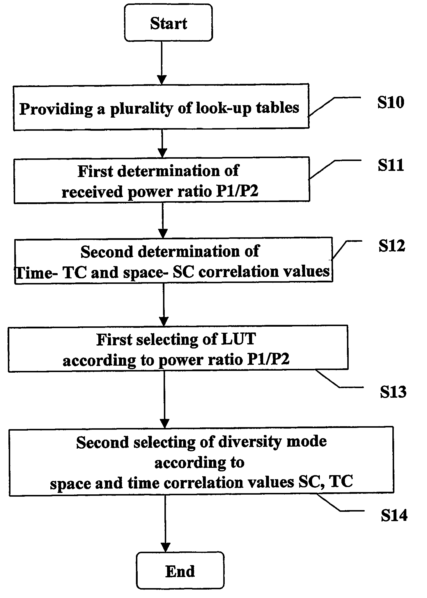
[0055] In the following, the proposed mode selection procedure according to the present invention is outlined. It is to be noted that in the be low procedure all steps are performed in the transmitter (e.g. BS). The procedure as such basically comprises the following steps when selecting a diversity mode A, B, C to be applied by a transmitter having two cross-polarized antenna arrays Ant1, Ant 2, each representing a diversity branch, for transmission diversity.

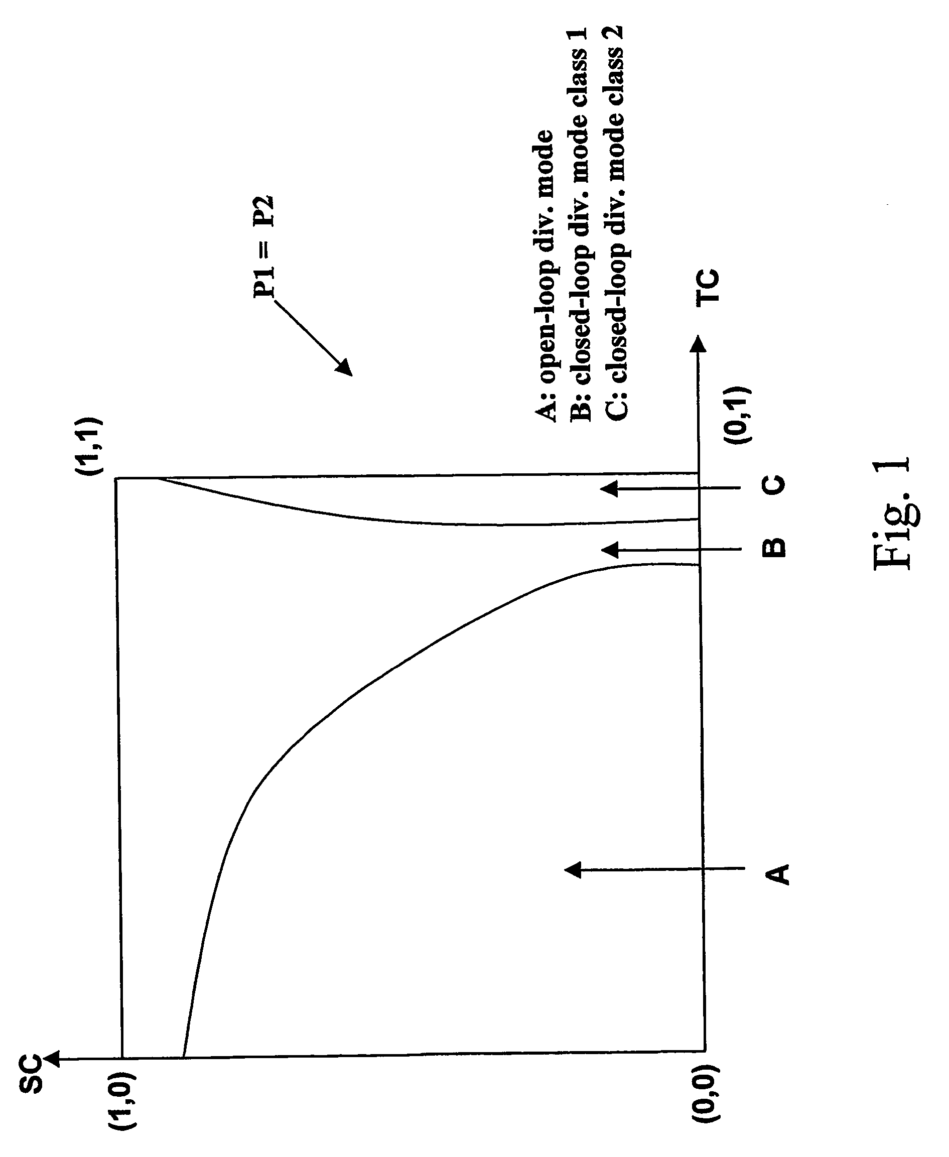
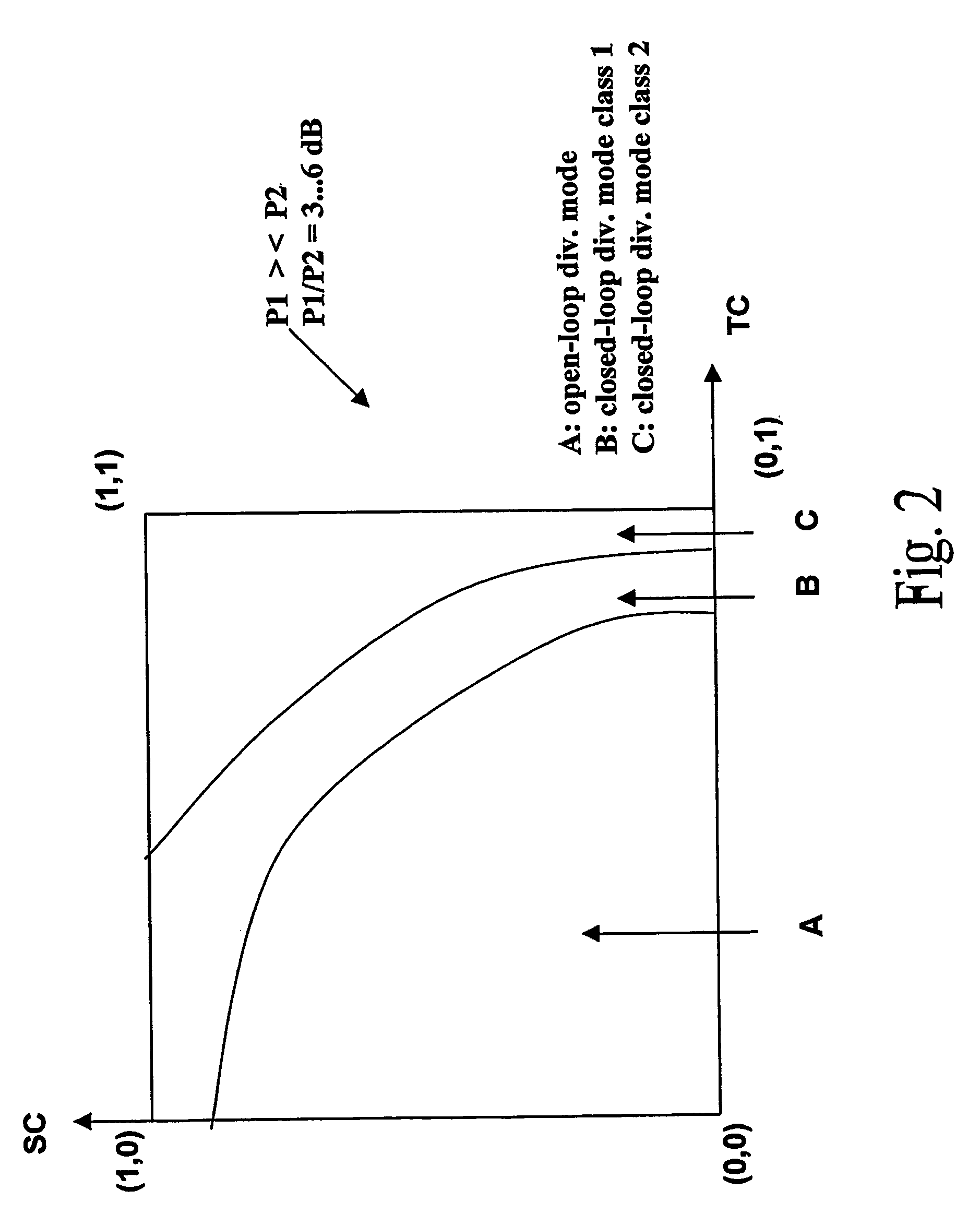
[0056] Firstly, a plurality of diversity mode performance chart look-up tables LUT, LUT1, LUT2, LUT3 are provided, step S10. Each performance chart look-up table maps a respective individual diversity mode A, B, C out of a plurality of individual diversity modes to a respective pair of time correlation value TC and space correlation value SS for said two cross-polarized antennas, and a respective individual diversity mode is presented by a mapping, area (in the chart). The plurality of performance chart look-up tables is para...


PUM


Abstract

The present invention concerns a method for selecting a diversity mode (A, B, C) to be applied by a transmitter having two cross-polarized antenna arrays (Ant1, Ant 2), each representing a diversity branch, comprising the steps of: providing (S10) a plurality of diversity mode performance chart look-up tables (LUT, LUT1, LUT2, LUT3), mapping a respective individual diversity mode (A, B, C) to a respective pair of time correlation value (TC) and space correlation value (SC) for said two cross-polarized antenna array beams, wherein a respective individual diversity mode is presented by a mapping area, wherein the plurality of performance chart look-up tables is parameterized by an indication of a ratio (P1/P2) of received powers from said diversity branches, first selecting (S13) one of said performance chart look-up tables dependent on determined ratio (P1/P2) of received powers from separate beams, and second selecting (S14) one of said individual diversity modes (A, B, C) according to the mapping to the determined actual time 303 relation (TC) and space correlation (SC) values from said first selected performance chart look-up table.

Description

FIELD OF THE INVENTION [0001] The present invention relates to a method for selecting a diversity mode to be applied by a transmitter having two cross-polarized antenna arrays. BACKGROUND OF THE INVENTION [0002] In detail, the present invention relates to the field of transmit antenna diversity. A rather comprehensive introduction to the technical filed of diversity is for example given by Juha Korhonen in “Introduction to 3G mobile communications”, chapter 3.4., page 86 to 94, Artech House mobile communications series, 2001. More specifically, The concern of this invention resides in a mode selection procedure by which a suitable transmit diversity mode for each link in the cell defined by the coverage area of the subject transmitter can be selected. [0003] It is to be noted that while reference is made to an antenna array, an array comprising a single antenna only may still be regarded as an antenna array. Likewise, an antenna and / or antenna element of the array produces a beam of...

Claims


Application Information

Patent Timeline
IPC IPC(8): H04B7/06H04B7/10
CPCH04B7/0617H04B7/10H04B7/0689H04B7/0634H04B7/0654
Inventor HAMALAINEN, JYRI K.WICHMAN, RISTO
Owner NOKIA SOLUTIONS & NETWORKS OY
Why Eureka
Try Eureka