Rotary impact tool

a rotary impact and tool technology, applied in the field of rotary impact tools, can solve the problems of increasing the coast and upsizing of the rotary impact tool, reducing usability, and estimating the fastening torque, and achieve the effects of low speed, low fastening torque, and high speed

Active Publication Date: 2005-12-01
MATSUSHITA ELECTRIC WORKS LTD
View PDF9 Cites 64 Cited by
  • Summary
  • Abstract
  • Description
  • Claims
  • Application Information

AI Technical Summary

Benefits of technology

[0008] A purpose of the present invention is-to provide a rotary impact tool, which is usable in a work in which finish precision is emphasized, and can control proper torque control in a wide range of fastening torque with low cost.
[0010] By such a configuration, it is possible to set the fastening torque can be set optionally corresponding to the kind of fastening work. Foe example, when an object to be fastened by a fastening member such as a screw is a plaster board which needs low speed and low fastening torque, it is possible that the fastening torque can be set to be smaller value. Thus, the rotary impact tool can be used for a work in which the precision and finishing of the fastening of the fastening member is important. Alternatively, when an object to be fastened by a fastening member such as a bolt is a steel plate which needs high speed and high fastening torque, it is possible that the fastening torque can be set to be larger value. Thus, the rotary impact tool can be used for a work in which the speed of fastening work is required. Consequently, it is possible to provide a rotary impact tool, which is usable in a work in which finish precision is emphasized, and can control proper torque control in a wide range of fastening torque with low cost.

Problems solved by technology

It causes not only increase of coast and upsizing of the rotary impact tool but also decrease of usability.
Thus, the fastening torque is estimated with various methods and the fastening torque is limited with the estimated value in the conventional rotary impact tool.
However, when the conventional rotary impact tool is used for fastening an object with a light load, the object, for example, a fastening member such as a bolt will be damaged by several times of impacts or over fastening occurs, even though the fastening torque is set to be the smallest value.
Thus, the conventional rotary impact tool is rarely used for a work such as an interior finish work in which the finish precision is emphasized.
The actual fastening torque, however, is largely different from the desired fastening torque, so that over fastening due to the damage of the object to be fastened or under fastening due to loosening the fastening member occurs.
The rotary impact tool with using a driving source moved by a battery, however, has a problem that the fastening torque largely varies due to voltage drop of the battery.
In addition, it is largely affected by property such as hard or soft of the object to be fastened by the fastening member.
Since the impact energy is calculated with the rotation speed of the output shaft at instant of impact, it needs a high resolution sensor and high speed processor which cause to increase of cost.

Method used


Image

  • Rotary impact tool
  • Rotary impact tool
  • Rotary impact tool

Examples


Embodiment Construction

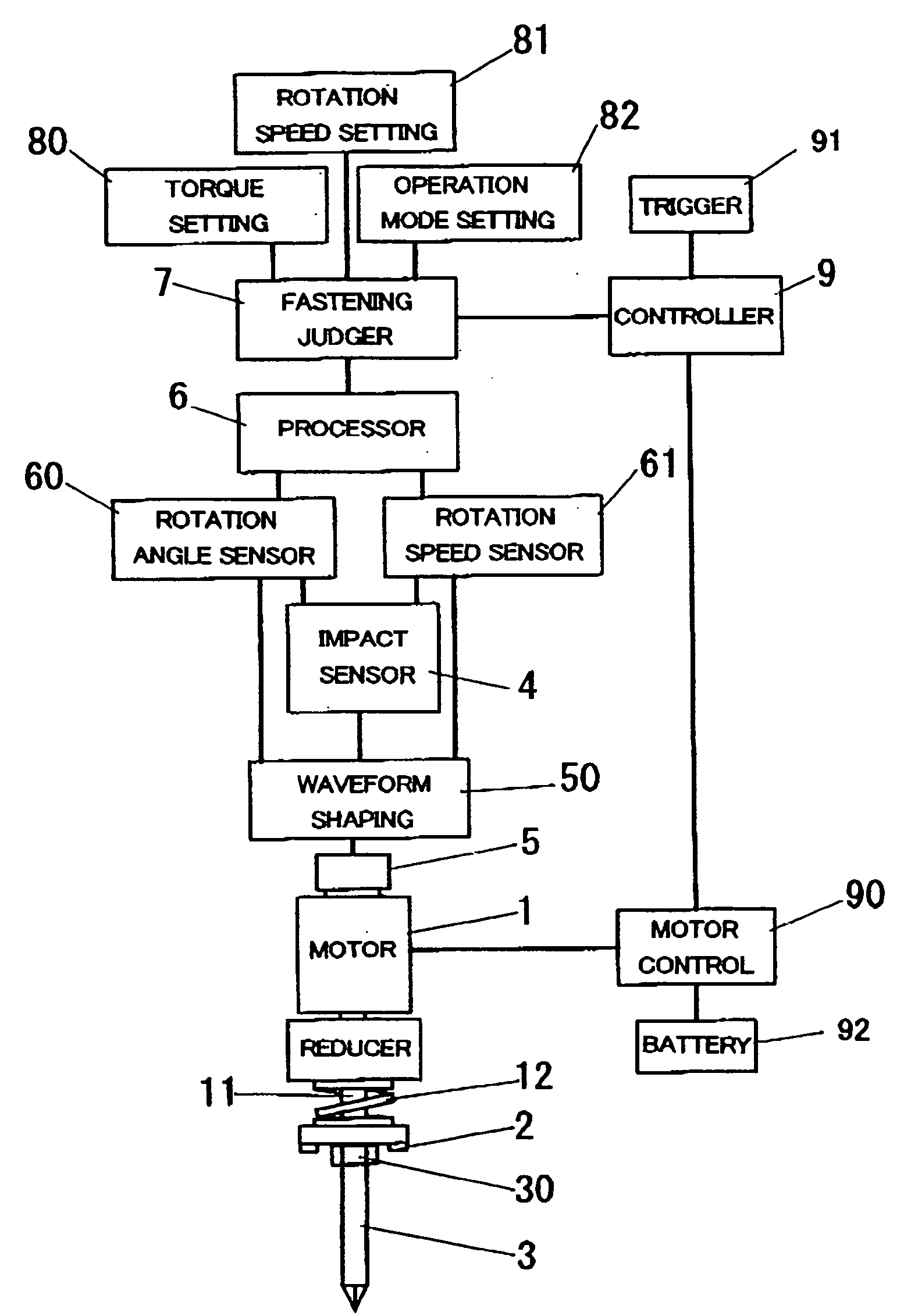
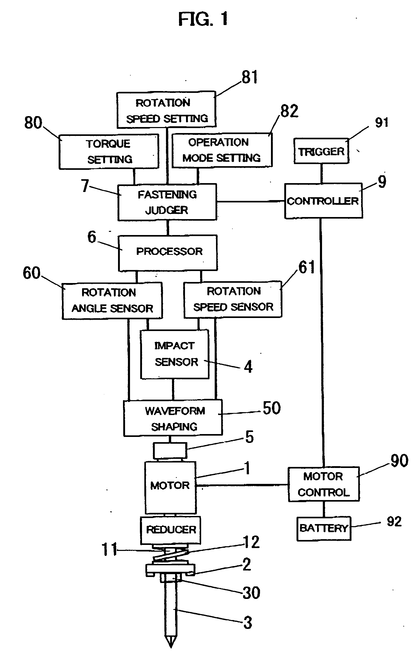
[0017] A rotary impact tool in accordance with an embodiment of the present invention is described. A configuration of the rotary impact tool is shown in FIG. 1. The rotary impact tool comprises a rotary driving mechanism including a motor 1 as a driving source. The rotation force of the motor 1 is transmitted to a driving shaft 11 via a reducer having a predetermined reduction ratio. A hammer 2 is provided on the driving shaft 11 via a cam mechanism (not illustrated), and the hammer 2 is pressed toward an output shaft 3 by a spring 12.

[0018] The output shaft 3 has an anvil 30 which further comprises an engaging portion for engaging with the hammer 2 in the rotary direction of the output shaft 3. When no load is applied to the output shaft 3, the hammer 2 rotates with the output shaft 3. alternatively, when a load equal to or larger than a predetermined value is applied to the output shaft 3, the hammer 2 moves backward against the pressure of the spring 12, and turns to move forwa...


PUM

PropertyMeasurementUnit
rotation angle Δraaaaaaaaaa
rotation angleaaaaaaaaaa

Abstract

A rotary impact tool can be used in a work especially precision or finishing of fastening is important. The rotary impact tool comprises a rotary driving mechanism including a driving source for rotating a driving shaft, a hammer fixed on the driving shaft, an output shaft to which a driving force is applied by impact blow of the hammer, a torque setting unit used for setting a fastening torque, a processor for calculating fastening torque from impact blow of the hammer, a rotation speed setting unit used for setting rotation speed of the driving shaft, and a controller for rotating the driving shaft of the rotary driving mechanism in a rotation speed set in the rotation speed setting unit and for stopping rotation of the driving shaft of the rotary driving mechanism when the fastening torque calculated in the processor becomes equal to or larger than a reference value of fastening torque previously set in the torque setting unit.

Description

BACKGROUND OF THE INVENTION [0001] 1. Field of the Invention [0002] The present invention relates to a rotary impact tool such as an impact wrench or an impact driver used for fastening or loosening of fastening member such as a screw, a bolt or a nut. [0003] 2. Description of the Related Art [0004] In a rotary impact tool used for fastening a member to be fastened such as a bolt or a nut, it is desirable that a driving source is stopped for completing fastening operation when a fastening torque reaches to a predetermined set value. Although measurement of actual fastening torque is most desirable at point of precision of fastening, it is necessary to provide a torque sensor in an output shaft of the rotary impact tool. It causes not only increase of coast and upsizing of the rotary impact tool but also decrease of usability. Thus, the fastening torque is estimated with various methods and the fastening torque is limited with the estimated value in the conventional rotary impact too...

Claims


Application Information

Patent Timeline
Patent Type & Authority Applications(United States)
IPC IPC(8): B25B21/02B25B23/14B25D1/00
CPCB25B23/1405B25B21/026
Inventor SAINOMOTO, YOSHINORIMATSUMOTO, TATSUHIKOARIMURA, TADASHIOHASHI, TOSHIHARUSHIMIZU, HIDENORISAWANO, FUMIAKI
Owner MATSUSHITA ELECTRIC WORKS LTD
Why Eureka
Try Eureka