

Sound-absorbing structure and sound-absorbing unit
a technology of sound absorption structure and sound absorption unit, which is applied in the direction of walls, instruments, transportation and packaging, etc., can solve the problems of large energy loss of sound waves coming from the side of the support base, and the inability of the vibration of the support base to be transmitted directly to the corrugated partition plate, etc., to achieve efficient sound absorption, high sound absorption capability, and high sound absorption capacity
- Summary
- Abstract
- Description
- Claims
- Application Information
AI Technical Summary
Benefits of technology
Problems solved by technology
Method used
Image

Examples
first embodiment
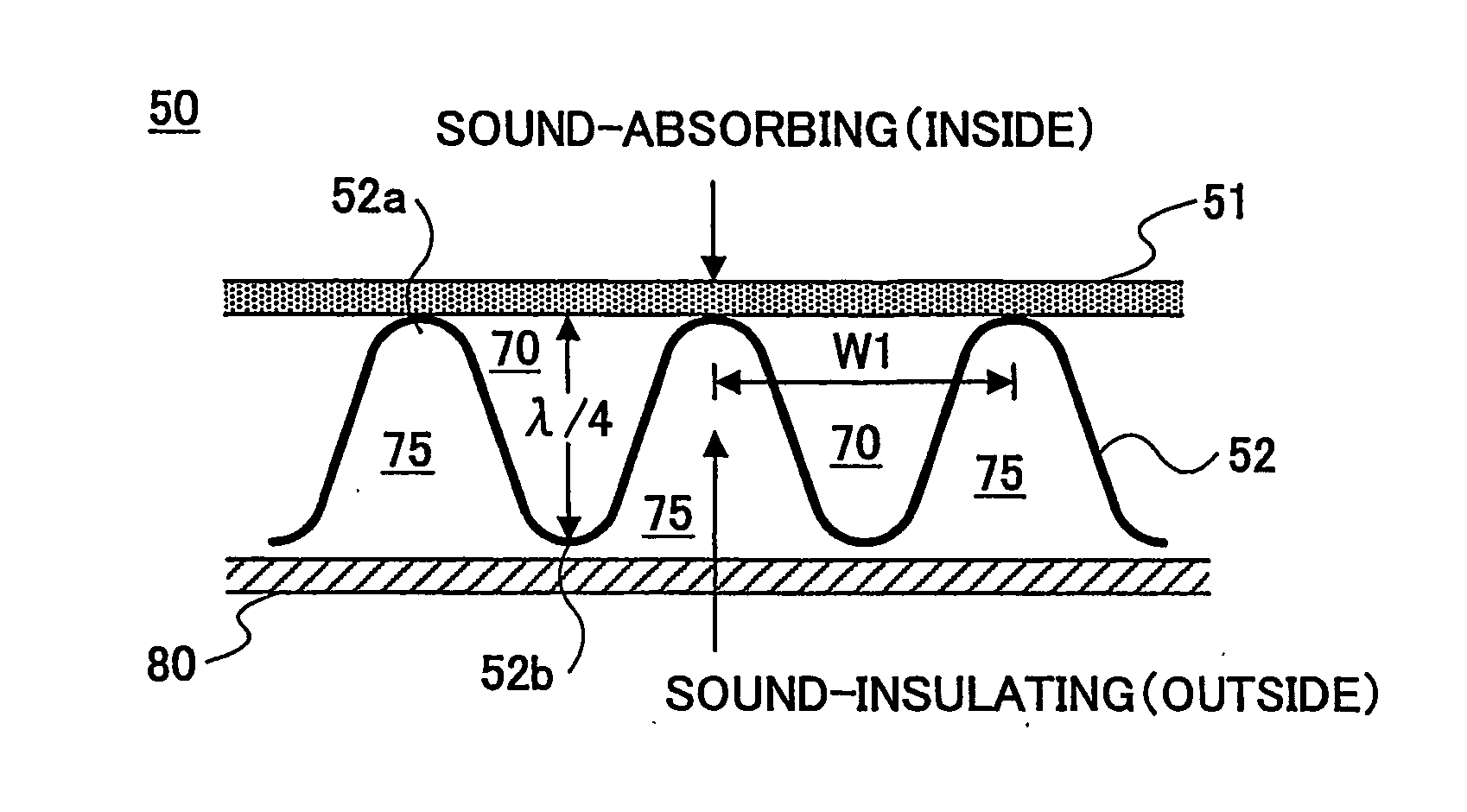
[0049]FIG. 3A is a cross-sectional view of a sound-absorbing unit according to the present invention. FIG. 3B is a perspective view of the partition plate of the sound-absorbing unit of this embodiment. The sound-absorbing unit 50 consists of a sound-absorbing material 51 and a partition plate 52.
[0050] The partition plate 52 according to the first embodiment has a wave-shaped cross-section with the upper and lower antinode portions 52a, 52b, respectively, extending substantially in parallel with each other in a constant direction. Although the corrugated partition plate 52 is made of stamped aluminum plate in terms of weight reduction, it can be made of hard resin such as polypropylene-based resin or steel, etc.
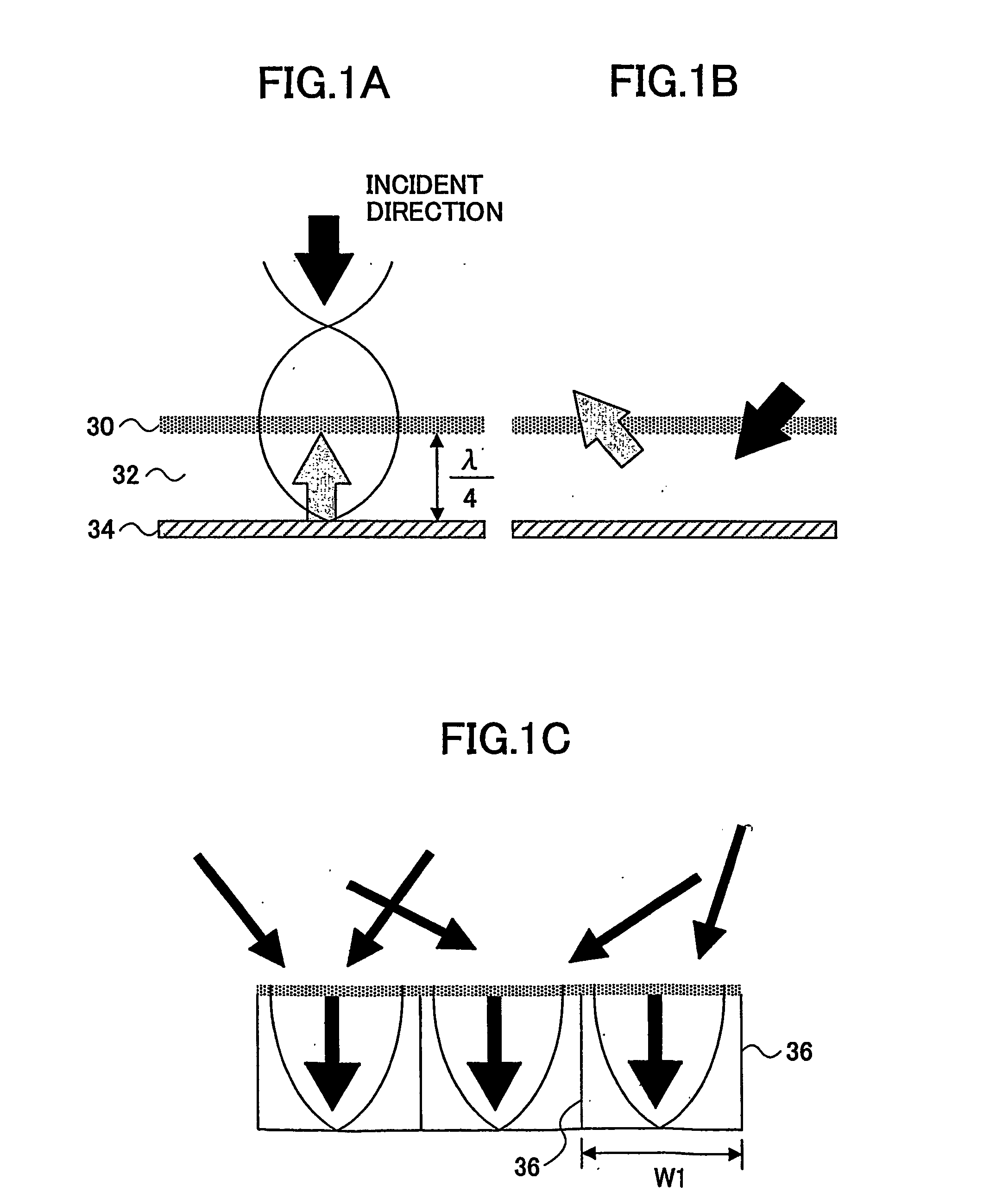
[0051] The pitch W1 between the neighboring upper antinode portions 52a may be determined, based on the above-mentioned principle, considering the target frequency band and the characteristics of the sound field around the sound-absorbing unit 50. It is noted that each of t...
second embodiment
[0073]FIG. 6A is a cross-sectional view of a sound-absorbing unit according to the present invention. FIG. 6B is a perspective view of the partition plates of the sound-absorbing unit of this embodiment. The sound-absorbing unit 60 consists of a sound-absorbing material 51, a partition plate 52 and second partition plates 53. The sound-absorbing material 51 and the partition plate 52 can be configured as the aforementioned embodiments (including alternative embodiments). The like components indicated by like references are the same as the aforementioned ones, unless otherwise specified.
[0074] The second partition plates 53 are substantially rectangular flat plate. The second partition plates 53 may be made of an aluminum or steel plate, as is the partition plate 52. According to this embodiment, the second partition plates 53 are placed in the direction X that is substantially perpendicular to the direction Y in which the antinode portions 52a, 52b of the corrugated partition plate ...
third embodiment
[0088]FIG. 11A is a cross-sectional view of a sound-absorbing unit according to the present invention. FIG. 11B is a perspective view of the partition plate of the sound-absorbing unit of this embodiment. The sound-absorbing unit 70 consists of a sound-absorbing material 51 and a partition plate 54. The sound-absorbing material 51 can be configured as in the aforementioned embodiments.
[0089] The sound-absorbing unit 70 of this embodiment may be configured and placed as in the aforementioned embodiments (see FIGS. 4A-4C and FIG. 7). For example, the sound-absorbing unit 70 may be mounted on the support base 80 via the elastic element 90, as shown in FIG. 11A. It is noted that elastic element 90 can be a low-destiny sheet material because the partition plate 54 is equipped with the sound-insulating capability for noise coming from behind, as the corrugated partition plate 52 mentioned above.
[0090] According to this embodiment, the partition plate 54 is made of aluminum plate, etc. wh...
PUM
 Abstract
Description
Claims
Application Information