Floor panel structure of vehicle body

a technology of floor panels and vehicle bodies, which is applied in the direction of roofs, transportation and packaging, vehicle arrangements, etc., can solve the problems of improper weight increase, uncomfortable vibration and noise generation in the cabin, and road noise, so as to reduce vibration energy and reduce acoustic emission

Inactive Publication Date: 2005-12-01
MAZDA MOTOR CORP
View PDF3 Cites 8 Cited by
  • Summary
  • Abstract
  • Description
  • Claims
  • Application Information

AI Technical Summary

Benefits of technology

[0009] The present invention has been devised in view of the above-described problems, and an object of the present invention is to provide a floor panel structure of a vehicle

Problems solved by technology

It is known that vibration from frame members coupled to the engine or the suspension of the vehicle is transmitted to floor panels and makes the floor panels and air in the cabin vibrate, resulting in uncomfortable vibration and noises being generated in the cabin.
The road noise is generally caused by resonance of vehicle tires and sympathetic vibration of the suspension.
However, in general a large amount of these materials are required, and thereby the weight of the vehicle body tend to increase improperly.
This overweight might cause various disadvantages including an issue of costs.
In this case,

Method used


Image

  • Floor panel structure of vehicle body
  • Floor panel structure of vehicle body
  • Floor panel structure of vehicle body

Examples


first embodiment

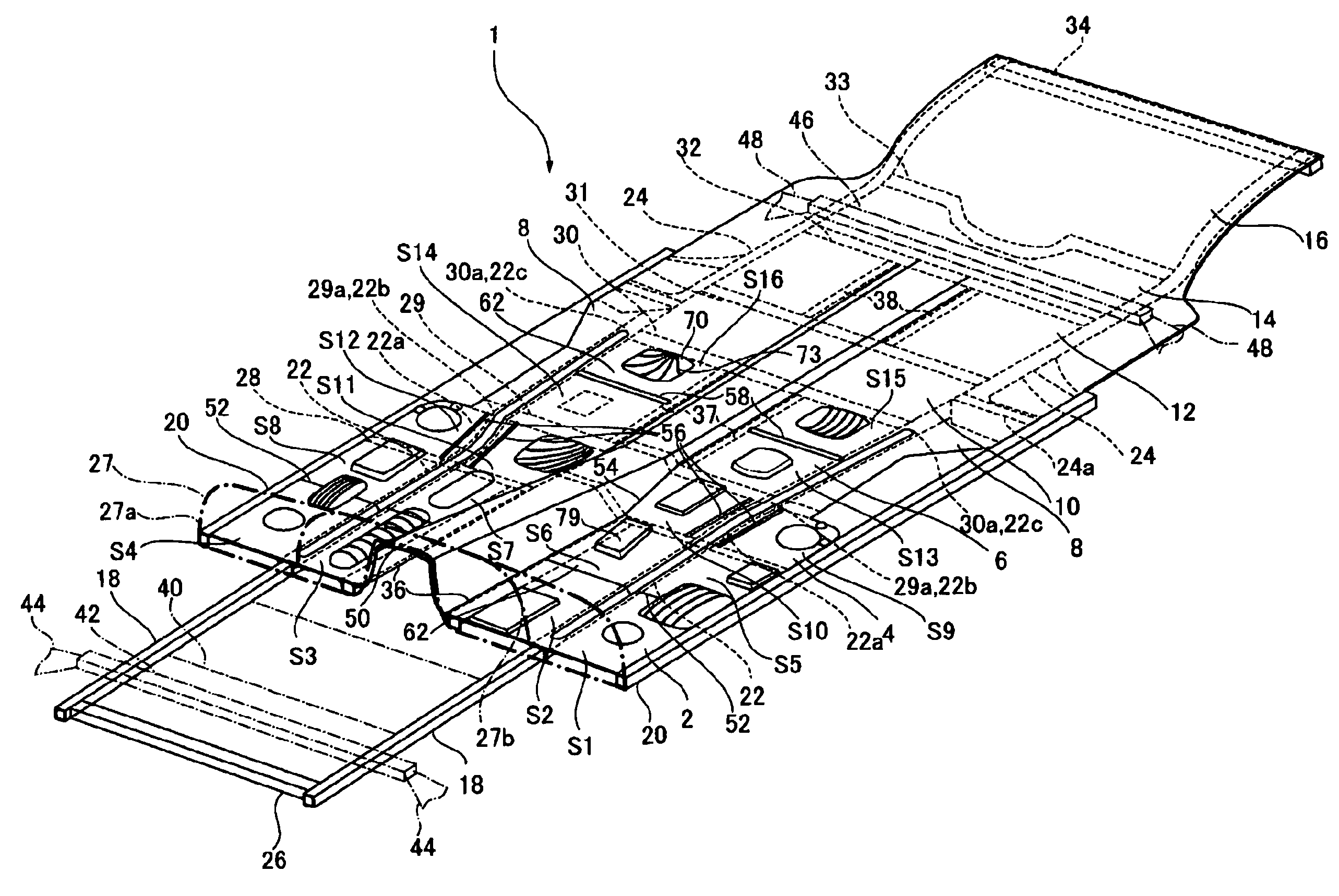
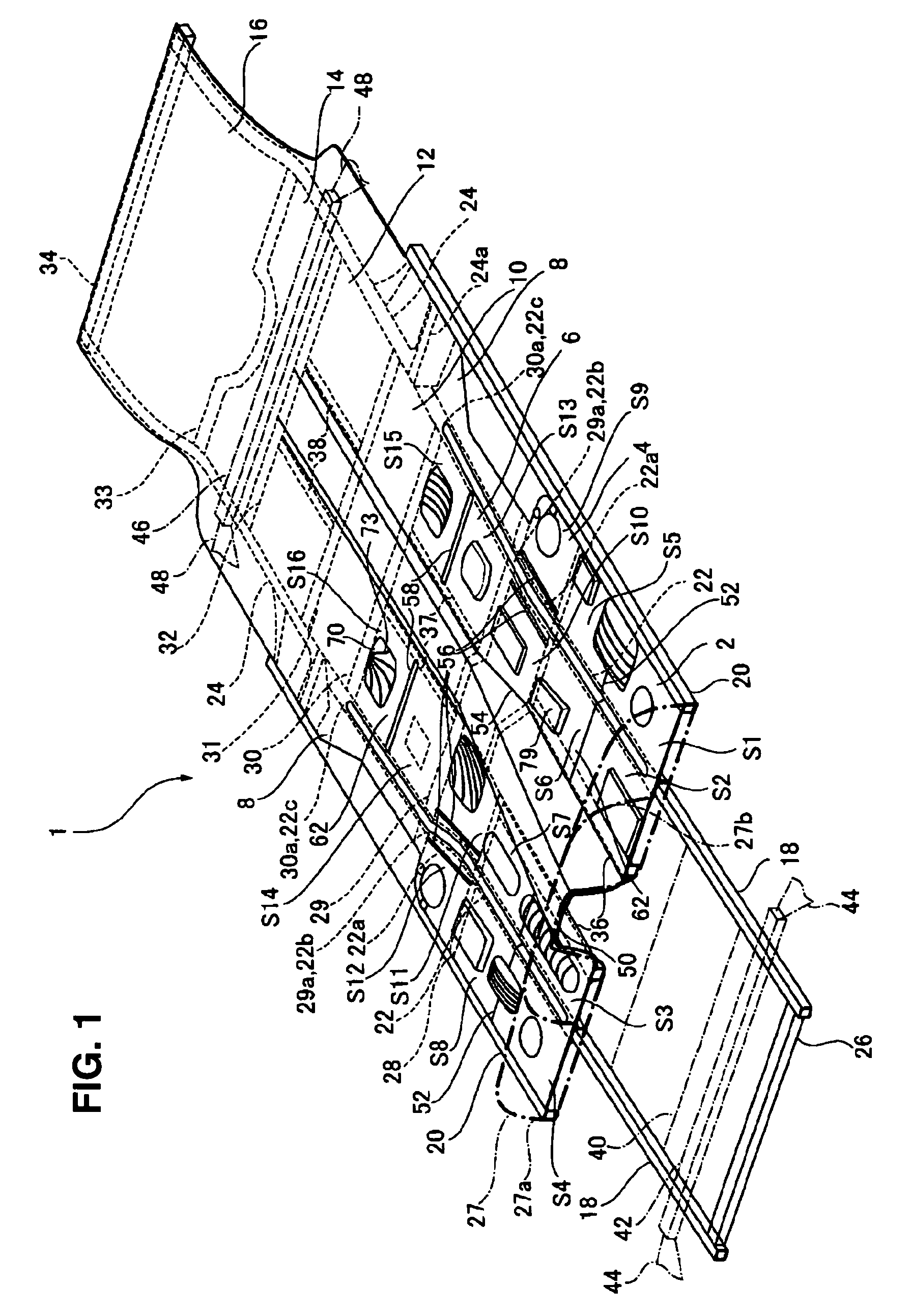
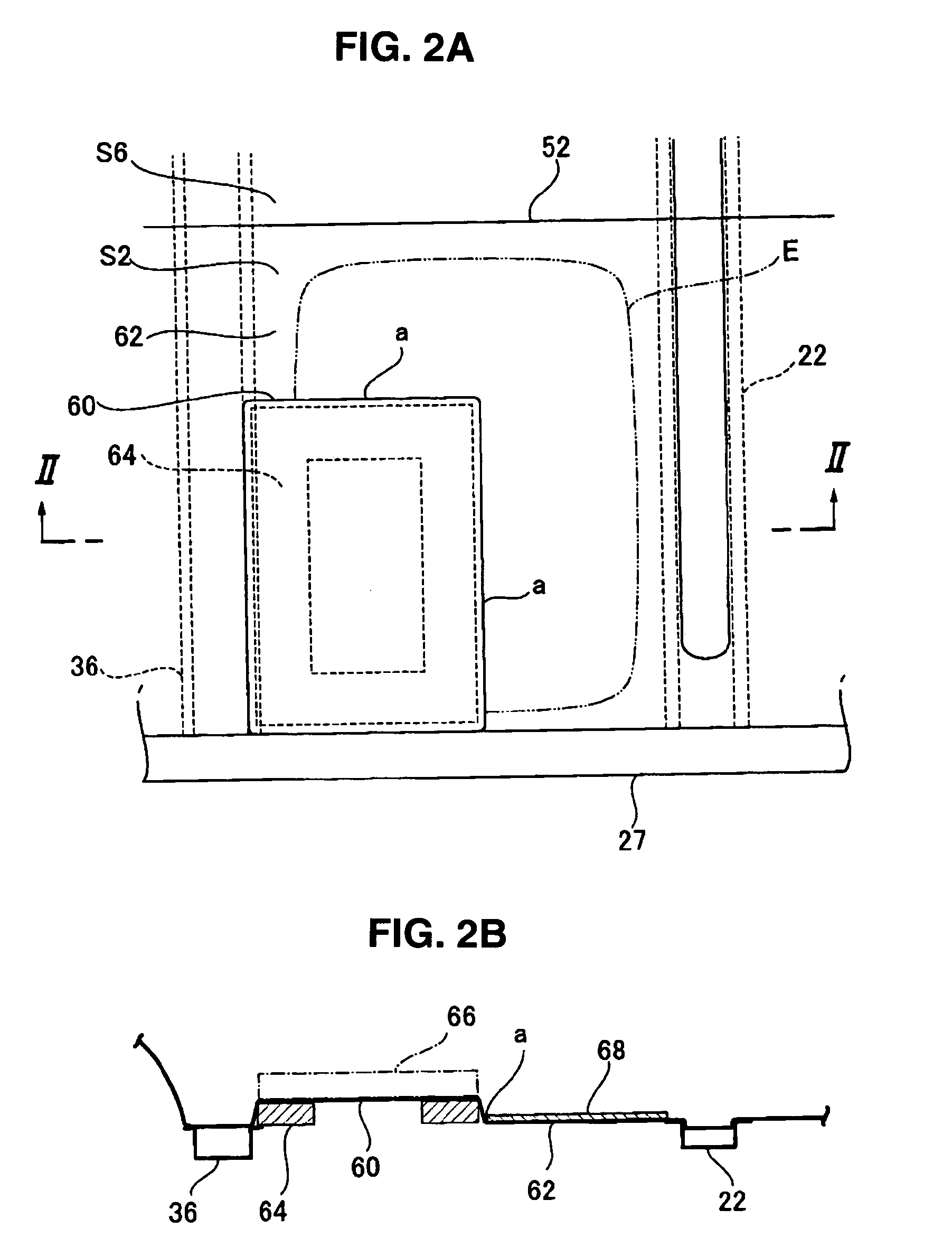
[0075] Next, function and effect of the floor panel structure will be described. Since the high-rigidity area 60 and the low-rigidity area 62 being provided around the high-rigidity area 60 are formed within the panel area S2, S10, S13 and S14 of the floor panel structure, the vibration energy is increased at the low-rigidity area 62 due to the difference in rigidity between the high-rigidity area 60 and the low-rigidity area 62. Further, since the auxiliary parts 66 is supported at the high-rigidity area 60, the rigidity of the high-rigidity area 60 is increased by the auxiliary parts 66 and thereby the above-described difference in rigidity is enhanced. Also, the auxiliary parts 66 increases the weight of the high-rigidity area 60, thereby increasing the difference in weight between the high-rigidity area 60 and the low-rigidity area 62. Accordingly, the vibration energy is further increased at the low-rigidity area 62 due to this difference in weight.

[0076] The vibration energy ...

third embodiment

[0165] Next, a modified embodiment of the third embodiment will be described referring to FIGS. 14 through 17. For example, in a case, as illustrated in FIG. 14, where there exists only one portion k having the smallest radius of curvature of the curved portion 20a at the panel area S9, the above-described flat portion 83 may be formed between this portion with the smallest radius of curvature and the first high-rigidity area 80. Herein, the same function and effect as those described above can be obtained. Particularly, since the flat area 83 is formed between this portion k and the first high-rigidity area 80, the first and second high-rigidity area 80, 81 and the flat area 83 are disposed between this portion k and the low-rigidity area 62, the rigidity of the low-rigidity area 62 can be prevented from being increased. As a result, the vibration energy can be increased at the low-rigidity area 62 effectively and surely.

[0166] Next, for example, in a case, as illustrated in FIG. 1...


PUM


Abstract

The panel area is formed in the substantially rectangular shape with sides thereof which extend substantially straight, by being enclosed by the frame member and the vibration restraint portion to control a vibration area, such as beads and the bent line portion, and the high-rigidity area and the low-rigidity area are formed within the panel area. Accordingly, the vibration energy can be increased at the low-rigidity area properly. As a result, the vibration energy transmitted from the frame members to the floor panel can be reduced, and thereby the acoustic emission generated from the floor panel can be reduced.

Description

BACKGROUND OF THE INVENTION [0001] The present invention relates to a floor panel structure of a vehicle body, particularly to a floor panel structure of a vehicle body in which a floor of an automotive vehicle is formed by a floor panel coupled to a plurality of frame members which extend in substantially longitudinal and width directions of the vehicle body. [0002] It is known that vibration from frame members coupled to the engine or the suspension of the vehicle is transmitted to floor panels and makes the floor panels and air in the cabin vibrate, resulting in uncomfortable vibration and noises being generated in the cabin. Herein, the vibration of engine itself and the road noise from the suspension are considered as vibration resources primarily. The road noise is generally caused by resonance of vehicle tires and sympathetic vibration of the suspension. [0003] Conventionally, damping materials or the like which are applied to the floor panels or the particular portions of th...

Claims


Application Information

Patent Timeline
IPC IPC(8): B60R13/08B62D21/15B62D25/20
CPCB60R13/083B62D25/2036B62D25/20
Inventor SUGIHARA, TSUYOSHINAKABAYASHI, SEIICHIHIRABAYASHI, SHIGEFUMI
Owner MAZDA MOTOR CORP
Why Eureka
Try Eureka