Vibration motor

a vibration motor and rotor technology, applied in the field of vibration motors, can solve the problems of reducing productivity, motor not driven, and the drawback of a large torque ripple in the related art vibration motor having two coils and six segments, so as to reduce the torque ripple and stabilize the torque of the rotor

Active Publication Date: 2005-12-01
TL ELECTRONICS CO LTD
View PDF3 Cites 4 Cited by
  • Summary
  • Abstract
  • Description
  • Claims
  • Application Information

AI Technical Summary

Benefits of technology

[0032] One object of the present invention is to provide a vibration motor that is capable of applying a stable torque to a rotor when a pair of brushes is disposed at an angle out of 90° therebetween.
[0033] Another object of the present invention is to provide a vibration motor that has a reduced torque ripple.

Problems solved by technology

In other words, the related art vibration motor having two coils and eight-segment commutator has a drawback in that death point occurs when the brush angle is out of 90°, such that the motor is not driven.
Therefore, the disclosed vibration motor requires a high voltage input for operation owing to the large torque ripple, thereby reducing productivity.
As described above, the related art vibration motor having two coils and eight-segment commutator has a drawback in that the death point occurs when the brush angle is out of 90°, such that the motor is not driven.
On the other hand, the related art vibration motor having two coils and six-segment commutator has a drawback that has a large torque ripple.

Method used


Image

  • Vibration motor
  • Vibration motor
  • Vibration motor

Examples


Embodiment Construction

[0059] Reference will now be made in detail to the preferred embodiments of the present invention, examples of which are illustrated in the accompanying drawings. Wherever possible, the same reference numbers will be used throughout the drawings to refer to the same or like parts.

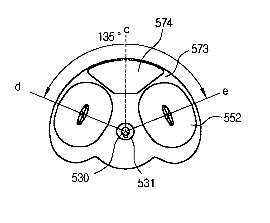
[0060]FIG. 7 is a sectional diagram of a vibration motor according to the present invention. FIGS. 8A and 8B are a top plan view and a bottom plan view of a rotor of a vibration motor according to the present invention.

[0061]FIG. 9 is a diagram illustrating an arrangement of contact points of brushes and poles of a magnet in a vibration motor, and FIG. 10 is an equivalent circuit diagram illustrating connections between coils and a commutator of a vibration motor according to the present invention.

[0062] As shown, the vibration motor of the present invention includes an upper case 510 and a lower case 520, which are coupled with each other.

[0063] A lower board 521 is attached on the lower case 520 and a...


PUM


Abstract

A vibration motor includes: a lower case provided with a lower board; an upper case coupled with the lower case; a four-pole magnet provided on the lower case; a shaft supported between the lower case and the upper case; a rotor rotatably supported by the shaft with an eccentricity, in which a pair of coils is provided in the rotor at an angle ranging form 135° to 142° between centerlines thereof; a commutator formed on a bottom of the rotor with six segments; and a pair of brushes having lower parts contacted with the lower board and upper parts contacted with the segments of the commutator at an angle of 90° therebetween.

Description

[0001] The present application is a continuation of co-pending U.S. patent application Ser. No. 10 / 865,926 filed on Jun. 14, 2004 for which priority is claimed under 35 U.S.C. § 120. This application also claims priority under 35 U.S.C. § 119(a) on Patent Application No(s). 10-2004-0029761 filed in Korea on Apr. 29, 2004. The entire contents of each of these applications are herein fully incorporated by reference.BACKGROUND OF THE INVENTION [0002] 1. Field of the Invention [0003] The present invention relates to a vibration motor, and more particularly, to a flat-type vibration motor. [0004] 2. Description of the Related Art [0005] Flat-type vibration motors are used to attain vibratory motion for silent call of personal information appliances, such as mobile communication terminal. [0006] A demand for the flat-type vibration motors are being increased as they are being used in mobile communication terminals for vibration means. A miniaturization and a lightweight are demanded for t...

Claims


Application Information

Patent Timeline
Patent Type & Authority Applications(United States)
IPC IPC(8): H02K7/075H02K7/06H02K23/28H02K23/54H02K23/58
CPCH02K7/063H02K23/58H02K23/54H02K23/28H02K7/075
Inventor PARK, YOUNG IL
Owner TL ELECTRONICS CO LTD
Why Eureka
Try Eureka