Lighting device for discharge lamp
- Summary
- Abstract
- Description
- Claims
- Application Information
AI Technical Summary
Benefits of technology
Problems solved by technology
Method used
Image
Examples
first embodiment
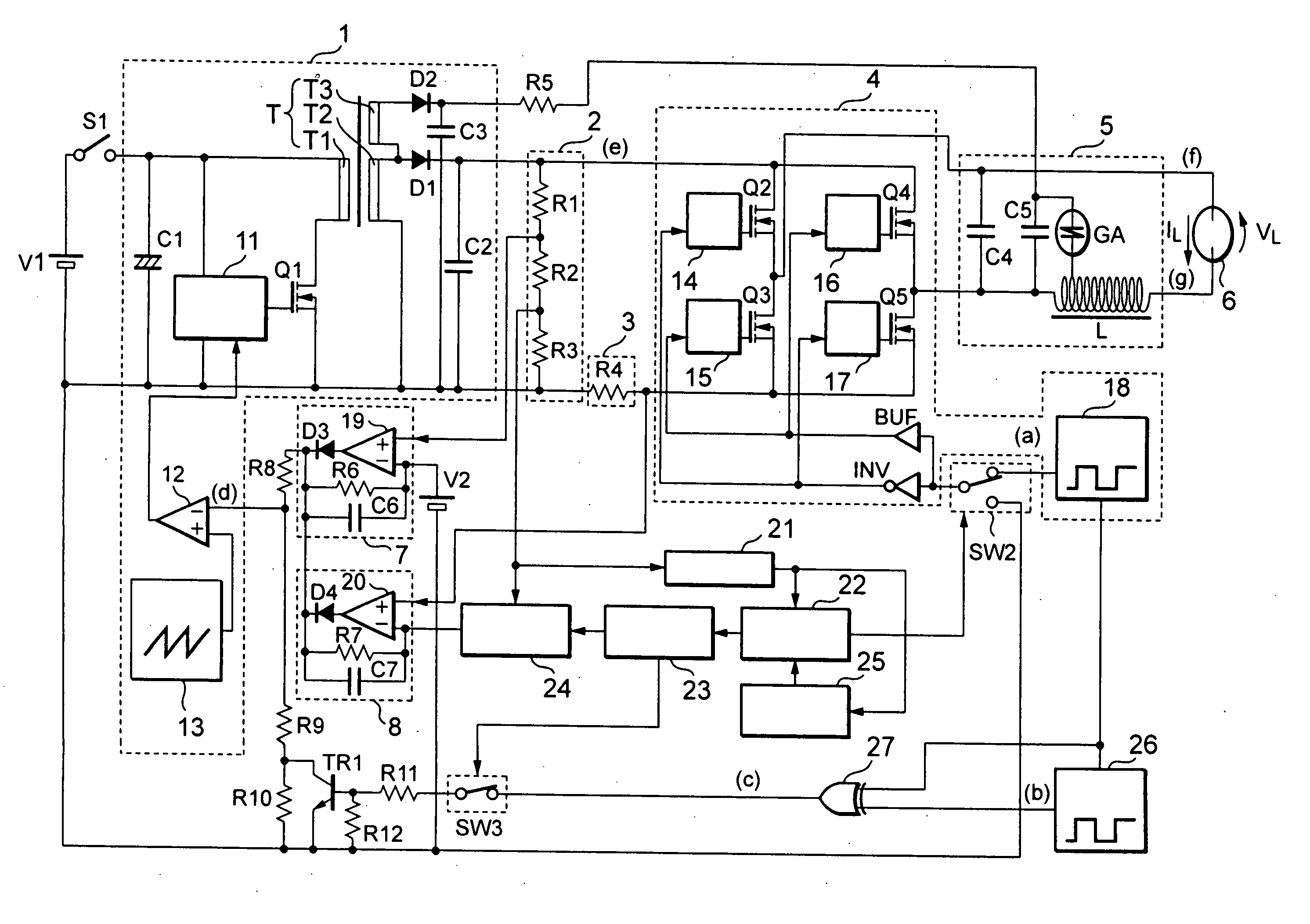
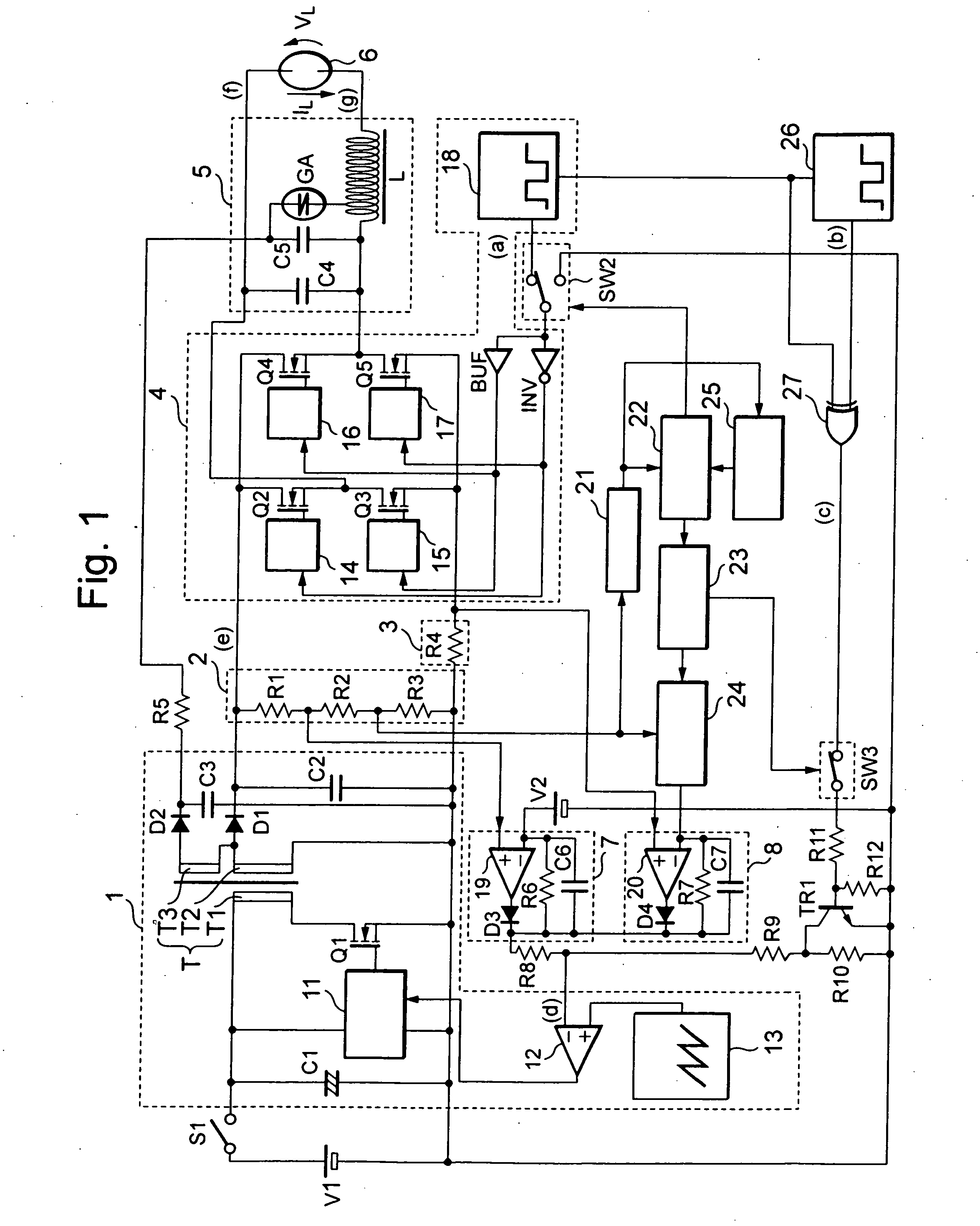
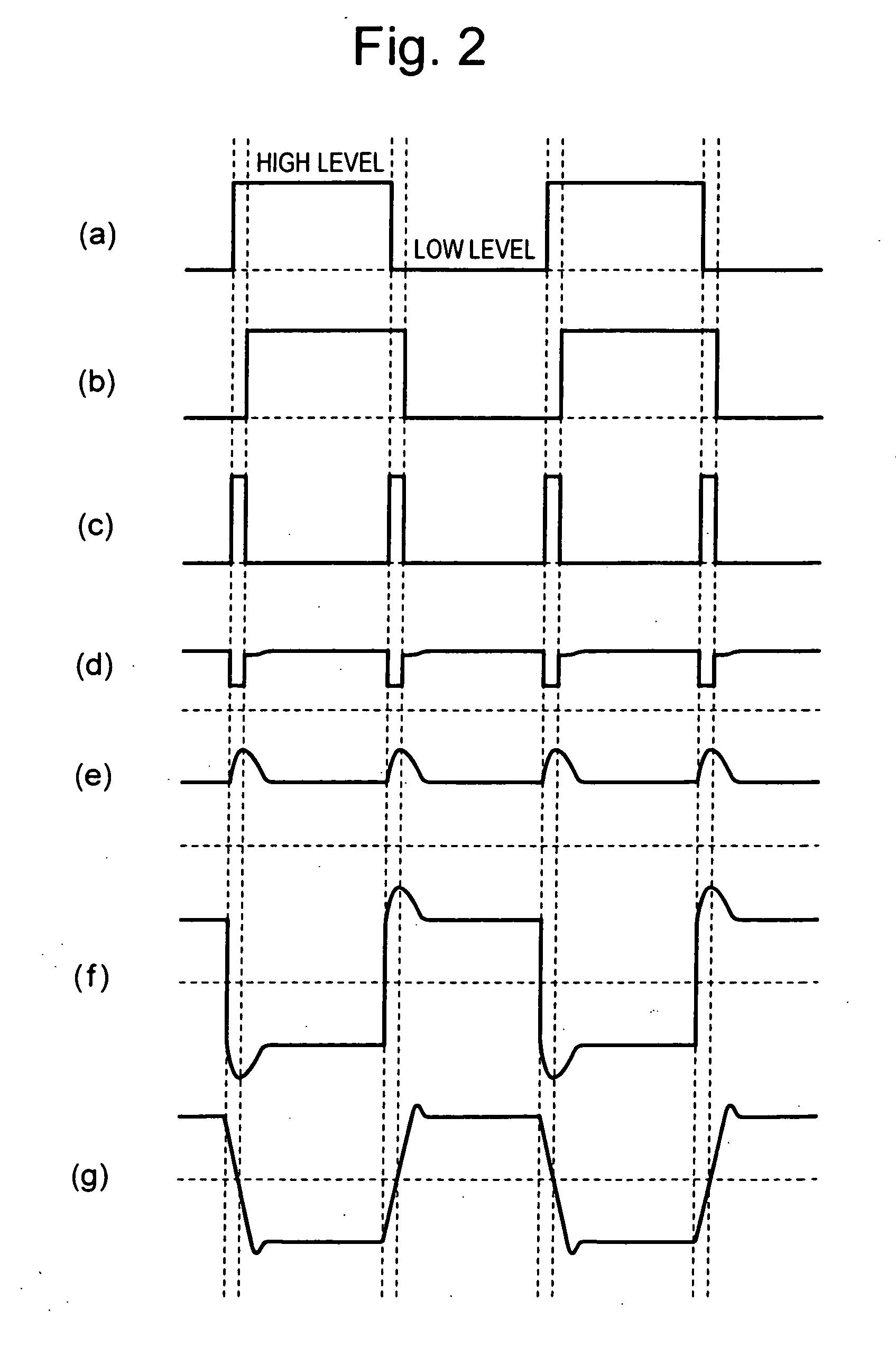
[0027]FIG. 1 shows a circuit configuration of the lighting device for high-pressure discharge lamp according to the first embodiment of the present invention.
[0028] The lighting device comprises a DC power source V1, a switch S1, a DC / DC converter circuit 1, an output voltage detecting circuit 2, an output current detecting circuit 3, a DC / AC inverter circuit 4, an igniter 5, a high-pressure discharge lamp 6 and a control circuit for controlling these.
[0029] In the DC / DC converter circuit 1, a primary side of a transformer T includes a capacitor C1, a switching element Q1, a power MOS drive circuit 11, a PWM comparator 12, a sawtooth-like wave generating circuit 13, and a transformer T1. A secondary side of the transformer T connected to the DC / AC inverter circuit 4 includes a transformer T2, a diode D1 and a capacitor C2, and a secondary side of the transformer T connected to the igniter 5 includes a transformer T3, a diode D2 and a capacitor C3.
[0030] A connecting relationship ...
second embodiment
[0073]FIG. 4. is a view showing a circuit configuration of a lighting device for high-pressure discharge lamp according to a second embodiment of the present invention. In the respective portions of the second embodiment, the same portions as the respective portions of the lighting device for high-pressure discharge lamp of the first embodiment of FIG. 1 designate the same reference numerals, and the description will be omitted.
[0074] The second embodiment differs from the first embodiment in the following point. Since the second embodiment is not a system for raising the output voltage of the DC / DC converter circuit 1 by regulating the duty ratio of the switching element Q1, only a signal from the differential amplifying circuit 7 or the differential amplifying circuit 8 affects the inverting input terminal of the PWM comparator 12.
[0075] Furthermore, a control circuit 28 including a function of the switch SW2 is connected instead of the buffer BUF, the inverter INV and the switc...
third embodiment
[0098] The present invention can be applied to, for example, a lighting device for a single-ended mold high-pressure discharge lamp, in which the temperature of the electrodes of the discharge lamp differ, such as a headlight of the automobile. Such an embodiment of the present invention will be described.
[0099] Generally, the single-ended mold high-pressure discharge lamp 30, such as a headlight of an automobile, has a structure as shown in FIG. 9. That is, metal foils 33a, 33b are respectively connected to electrodes 32a, 32b provided oppositely in a light emitting tube 31, and external lead wires 34a, 34b for applying a power from an outside source are respectively connected to these metal foils 33a, 33b. In the single-ended mold high-pressure discharge lamp of such a structure, as shown in FIG. 9, a heat is positively dissipated in a direction of a base, however, since the radiation of heat in an opposite direction is remarkably small as compared with the former direction, temp...
PUM
 Abstract
Description
Claims
Application Information
 - R&D
- Intellectual Property
- Life Sciences
- Materials
- Tech Scout
- Unparalleled Data Quality
- Higher Quality Content
- 60% Fewer Hallucinations
Browse by: Latest US Patents, China's latest patents, Technical Efficacy Thesaurus, Application Domain, Technology Topic, Popular Technical Reports.
© 2025 PatSnap. All rights reserved.Legal|Privacy policy|Modern Slavery Act Transparency Statement|Sitemap|About US| Contact US: help@patsnap.com


