
Power supply system for a vehicle

a power supply system and vehicle technology, applied in the direction of pulse technique, pedestrian/occupant safety arrangement, instruments, etc., can solve the problems of increasing current consumption in ecus (electronic control units), difficult to ensure the operation of the second power supply circuit, etc., to reduce the rating of the step-up circuit, reduce the control load, and increase the size

Inactive Publication Date: 2005-12-01
DENSO CORP
View PDF4 Cites 49 Cited by
  • Summary
  • Abstract
  • Description
  • Claims
  • Application Information

AI Technical Summary

Benefits of technology

[0011] The present invention therefore has an object to provide a power supply system for a vehicle having a vehicle device such as a passive safety device, wherein a vehicle device function is not impaired even at lower battery voltages, control load on a step-up circuit is reduced and increase in size and rating of the step-up circuit can be reduced.

Problems solved by technology

In this instance, the current consumption in ECUs (Electronic Control Units) is increased.
However, when the supply voltage from the battery 101 is lower than 6.5V, it is difficult to ensure the operation of the second power supply circuit 103.

Method used


Image

  • Power supply system for a vehicle
  • Power supply system for a vehicle
  • Power supply system for a vehicle

Examples


Embodiment Construction

[0022]

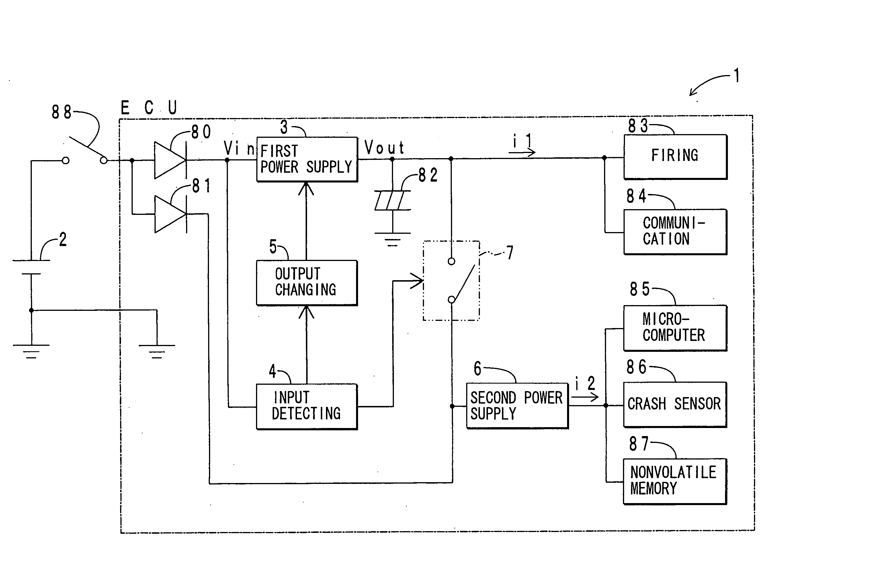
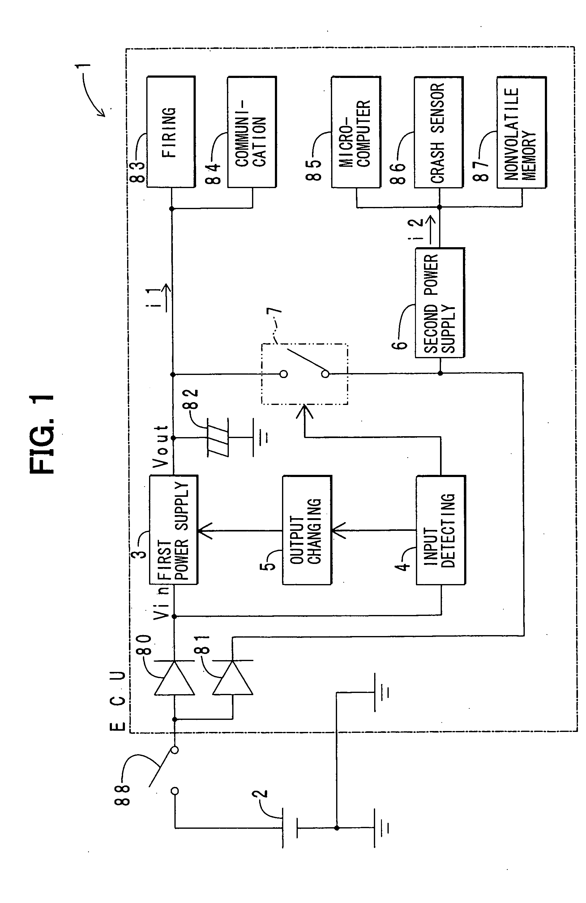
[0023] Referring first to FIG. 1, a power supply system 1 is applied to a passive safety device of a vehicle. It comprises a battery 2, a first power supply circuit 3, an input voltage detecting circuit 4, an output voltage changing circuit 5, a second power supply circuit 6, a switching element 7, reverse current blocking diodes 80 and 81, a backup capacitor 82, a firing circuit 83, a satellite sensor communication circuit 84, a microcomputer 85, a crash sensor 86, a nonvolatile memory 87 and an ignition switch 88. Of these elements, the first power supply circuit 3 is a step-up or booster circuit. The second power supply circuit 6 is a step-down circuit. The firing circuit 83 is one of actuators in the vehicle and the crash sensor 86 may be any type which responds to decelerations of the vehicle.

[0024] The battery 2 is mounted in the engine compartment (not shown) of the vehicle. The battery 2 is multipoint-connected on the high potential side with the reverse current block...


PUM


Abstract

In a power supply system for a passive safety device, a step-up circuit steps up an input voltage based on a supply voltage from a battery to obtain a predetermined output voltage. An input voltage detecting circuit detects the input voltage. An output voltage changing circuit changes the output voltage based on a detection signal from the input voltage detecting circuit. Thus, the control load on the step-up circuit is reduced and increase in the size and rating of the step-up circuit is suppressed.

Description

CROSS REFERENCE TO RELATED APPLICATION [0001] This application is based on and incorporates herein by reference Japanese Patent Application No. 2004-154730 filed on May 25, 2004. FIELD OF THE INVENTION [0002] The present invention relates to a power supply system for a vehicle having a vehicle device such as a passive safety device. BACKGROUND OF THE INVENTION [0003] A conventional power supply system 100 for a vehicle (for instance, JP 10-129402 A2 and JP 08-310337 A2), as illustrated in FIG. 7, comprises a battery 101, a first power supply circuit 102, a second power supply circuit 103, a firing circuit 104, a satellite sensor communication circuit 105, a microcomputer 106, a crash sensor 107, a nonvolatile memory 108 and a backup capacitor 109. [0004] The first power supply circuit 102 steps up or boosts an input voltage vin based on the supply voltage of the battery 101 to provide a predetermined high output voltage Vout (24V). The output voltage Vout is supplied to the firing c...

Claims


Application Information

Patent Timeline
IPC IPC(8): B60R16/03B60R16/02B60R21/01B60R21/16B60R22/46H02J7/00H02M3/155H03K3/00
CPCH02J7/0065B60R16/03H02J2207/20H02J7/0063H02J2310/46H02J7/007182
Inventor UENO, YUKIYASU
Owner DENSO CORP
Features
  • Generate Ideas
  • Intellectual Property
  • Life Sciences
  • Materials
  • Tech Scout
  • Unparalleled Data Quality
  • Higher Quality Content
  • 60% Fewer Hallucinations
Learn More