Liquid crystal display apparatus

Inactive Publication Date: 2005-12-01
PANASONIC LIQUID CRYSTAL DISPLAY CO LTD +1
View PDF6 Cites 146 Cited by
  • Summary
  • Abstract
  • Description
  • Claims
  • Application Information

AI Technical Summary

Benefits of technology

[0025] The display with high picture quality similar to that of the monitor can be carried. If it is used as a display of a cellular phone, image information of high picture quality can be reconstructed and the more advanced image information can be handled. Further, if it is used for a digital camera, an image before photographing and t

Problems solved by technology

Therefore, even if the phase differences among the liquid crystal layer and the plurality of retardation films and an axis layout are optimized in a normal direction, as a viewing point gets away from the normal direction, conditions rapidly deteriorate to be away from optimum conditions for the dark display.
Although the viewing angle dependency of the phase differences can be reduced by adjusting a refractive index in the thickness direction of the retardation films, it cannot be completely eliminated.
In the transflective IPS system, thus, an increase in dark display transmissive ratio in the obliqu

Method used


Image

  • Liquid crystal display apparatus
  • Liquid crystal display apparatus
  • Liquid crystal display apparatus

Examples


Example

Embodiment 1

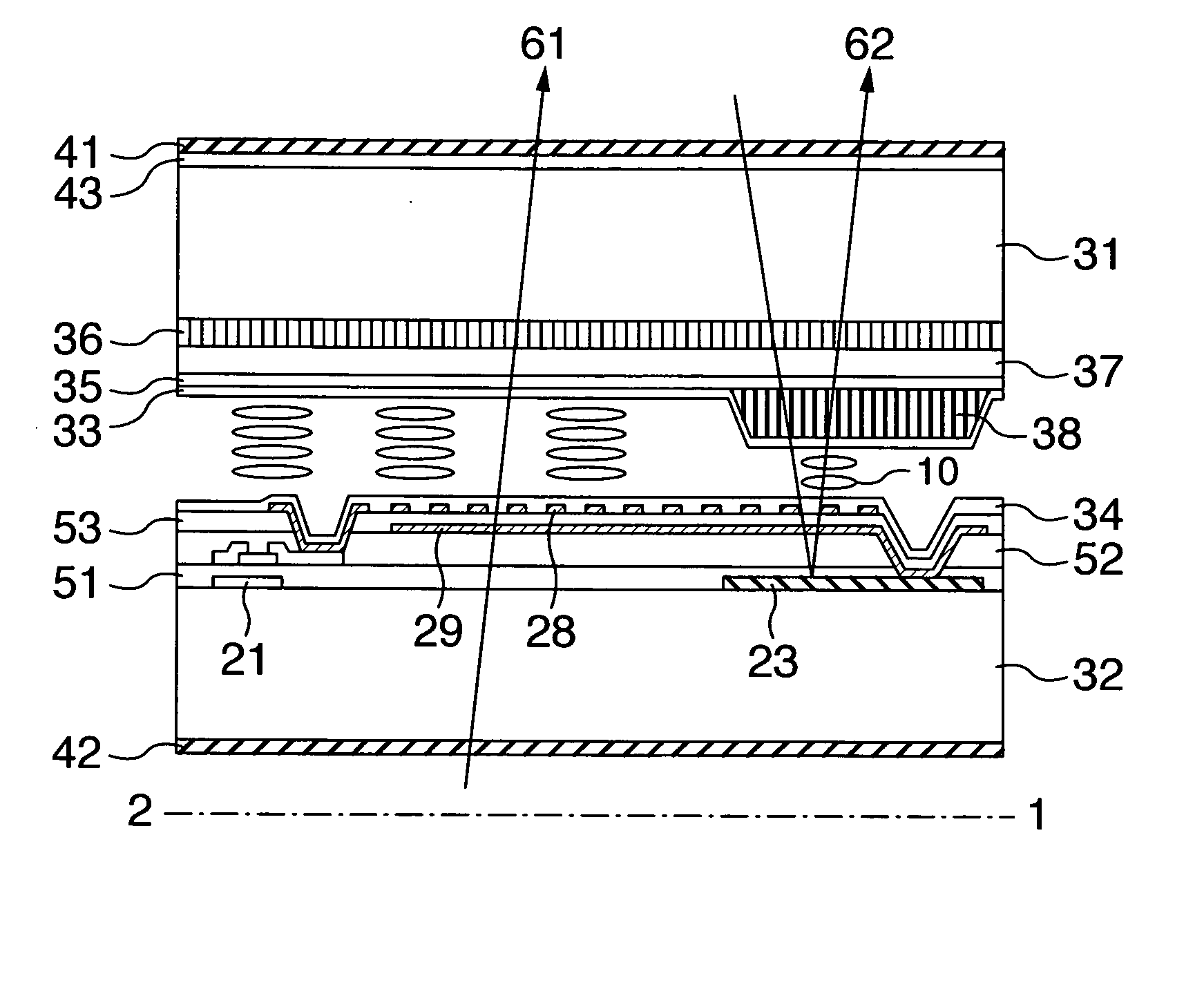
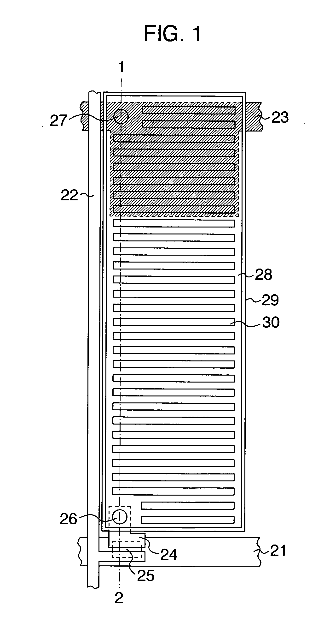
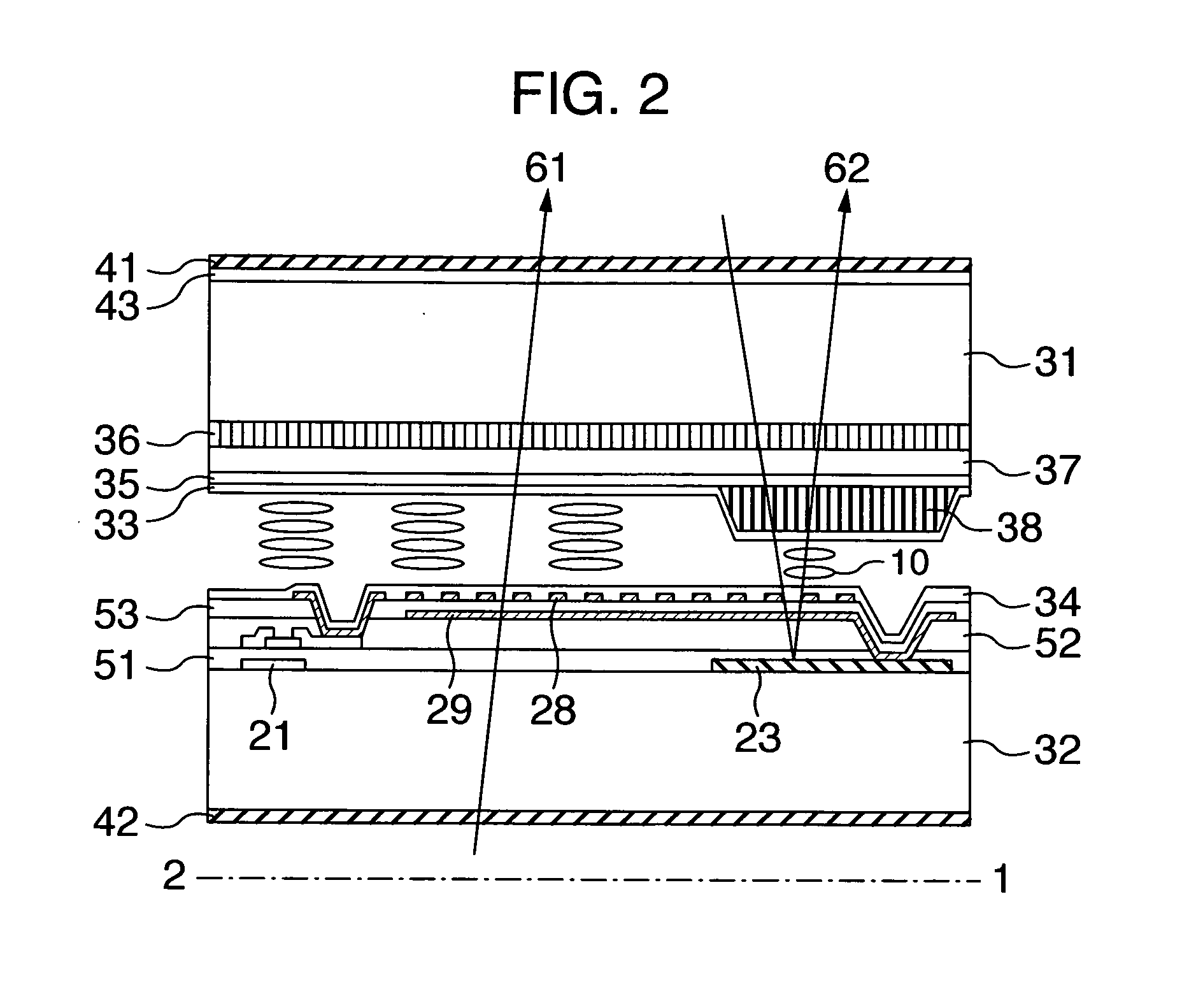
[0055] A cross sectional view of one pixel constructing a liquid crystal display according to the invention is shown in FIG. 2. A top view when a second substrate 32 is observed from the normal direction is shown in FIG. 1. A cross sectional view taken along an alternate long and short dash line 1-2 shown in FIG. 1 is also FIG. 2. The liquid crystal display of the invention is constructed mainly by a first substrate 31, a liquid crystal layer 10, and the second substrate 32. The liquid crystal layer 10 is sandwiched between the first substrate 31 and the second substrate 32. On the side near the liquid crystal layer 10, the first substrate 31 has a color filter 36, a leveling layer 37, a third alignment layer 35, an inner retardation layer 38, and a first alignment layer 33.

[0056] On the side near the liquid crystal layer 10, the second substrate 32 has a thin film transistor. The thin film transistor is connected to a scanning line 21, a signal line 22, and a pixel el...

Example

Embodiment 2

[0106] A cross sectional view of the liquid crystal display of the embodiment is shown in FIG. 12. In the embodiment, in the construction of the liquid crystal display of the embodiment 1, the inner retardation layer 38 is formed between the third alignment layer 35 and the color filter 36. Thus, the color filter 36, the leveling layer 37, and the first alignment layer 33 exist between the inner retardation layer 38 and the liquid crystal layer 10. There is a case where the non-reacted photoreactive liquid crystal and the initiator remain in the inner retardation layer 38. If they are mixed into the liquid crystal layer 10, there is a case where performance such as a holding ratio or the like deteriorates. If a number of films exist between the inner retardation layer 38 and the liquid crystal layer 10 as in the embodiment, since those films have a function of preventing the non-reactant and the initiator from being mixed into the liquid crystal layer 10, the performanc...

Example

Embodiment 3

[0108] In the embodiment, the inclining direction of the slits 30 of the pixel electrode 28 is set to two kinds. A plan view of one pixel of the transflective liquid crystal display of the embodiment is shown in FIG. 13. In the upper half portion and the lower half portion of the pixel, the slits 30 are inclined by −75° and 75° from the signal line 22, respectively. In association with it, as shown in FIGS. 14 and 15, the liquid crystal alignment direction 102, the slow axis direction 103 of the inner retardation layer 38, the transmissive axis 104 of the first polarization film 41, and the transmissive axis 106 of the second polarization film 42 are changed.

[0109] The liquid crystal alignment direction 102 is set to be perpendicular to the signal line direction 101. An angle between the liquid crystal alignment direction 102 and the electric field direction in the upper half portion of the pixel and that in the lower half portion are set to the same angle of 75°. The ...


PUM


Abstract

A liquid crystal display of a transflective IPS system in which a lateral electric field is applied to a liquid crystal layer. Polarization films are arranged on the entire surface of a transmissive display unit and a reflective display unit in a manner similar to a transmissive IPS system. An inner retardation layer whose retardation is equal to a half wave is formed in the reflective display unit. A retardation of the liquid crystal layer of the reflective display unit is set to a quarter wave. Thus, a reflective display can be performed in a wide range of environment from a light place to a dark place and a transmissive display of a wide viewing angle and high picture quality can be performed.

Description

CROSS-REFERENCE TO RELATED APPLICATION [0001] This application relates to U.S. Patent Application Serial No. not yet assigned based on Japanese Patent Application No. 2004-154780 filed May 25, 2005 entitled “LIQUID CRYSTAL DISPLAY APPARATUS” by Osamu ITO et al., the disclosure of which is incorporated herein by reference.BACKGROUND OF THE INVENTION [0002] 1. Field of the Invention [0003] The invention relates to a liquid crystal display which can display images in a wide range of environment from a light place to a dark place and execute a transmissive display with a wide viewing angle and high picture quality. [0004] 2. Description of the Related Art [0005] At present, a transmissive liquid crystal display of an IPS (In Plane Switching) system, a VA (Vertical Alignment) system, or the like has been spread as a monitor and is also used as a television by improving response performance. A liquid crystal display has also been spread to the fields of portable information apparatuses su...

Claims


Application Information

Patent Timeline
IPC IPC(8): G02B5/30G02F1/1333G02F1/1335G02F1/13363G02F1/1343
CPCG02F1/133371G02F1/133555G02F2413/09G02F2001/133565G02F1/134363G02F1/133565G02F1/133631
Inventor ITOU, OSAMUTANNO, JUNJIIMAYAMA, HIROTAKAOCHIAI, TAKAHIROMORIMOTO, MASATERU
Owner PANASONIC LIQUID CRYSTAL DISPLAY CO LTD
Why Eureka
Try Eureka