Beam focusing and scanning system using micromirror array lens

a micromirror array and beam focusing technology, applied in the field of optical systems, can solve the problems of low focusing efficiency, low reliability, and large power consumption of conventional variable focal length lenses, and achieve high speed variable focusing and scanning, large focal length variation, and high reliability and optical efficiency.

a micromirror array and beam focusing technology, applied in the field of optical systems, can solve the problems of low focusing efficiency, low reliability, and large power consumption of conventional variable focal length lenses, and achieve high speed variable focusing and scanning, large focal length variation, and high reliability and optical efficiency.

US20050264867A1Active Publication Date: 2005-12-01STEREO DISPLAY

Image

  • Beam focusing and scanning system using micromirror array lens
  • Beam focusing and scanning system using micromirror array lens
  • Beam focusing and scanning system using micromirror array lens

Examples


Embodiment Construction

[0046] The present invention will now be described in detail with reference to a few embodiments thereof as illustrated in the accompanying drawings. In the following description, numerous specific details are set forth in order to provide a thorough understanding of the present invention. It will be apparent, however, to one skilled in the art, that the present invention may be practiced without some or all of these specific details. In other instances, well known process steps and / or structures have not been described in detail in order to not unnecessarily obscure the present invention.

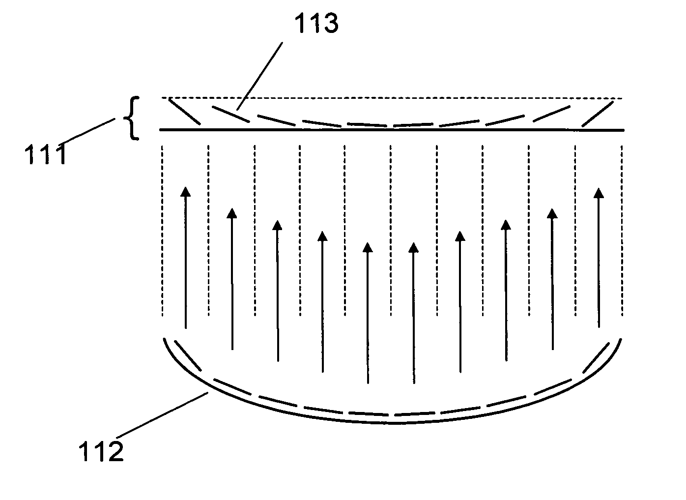
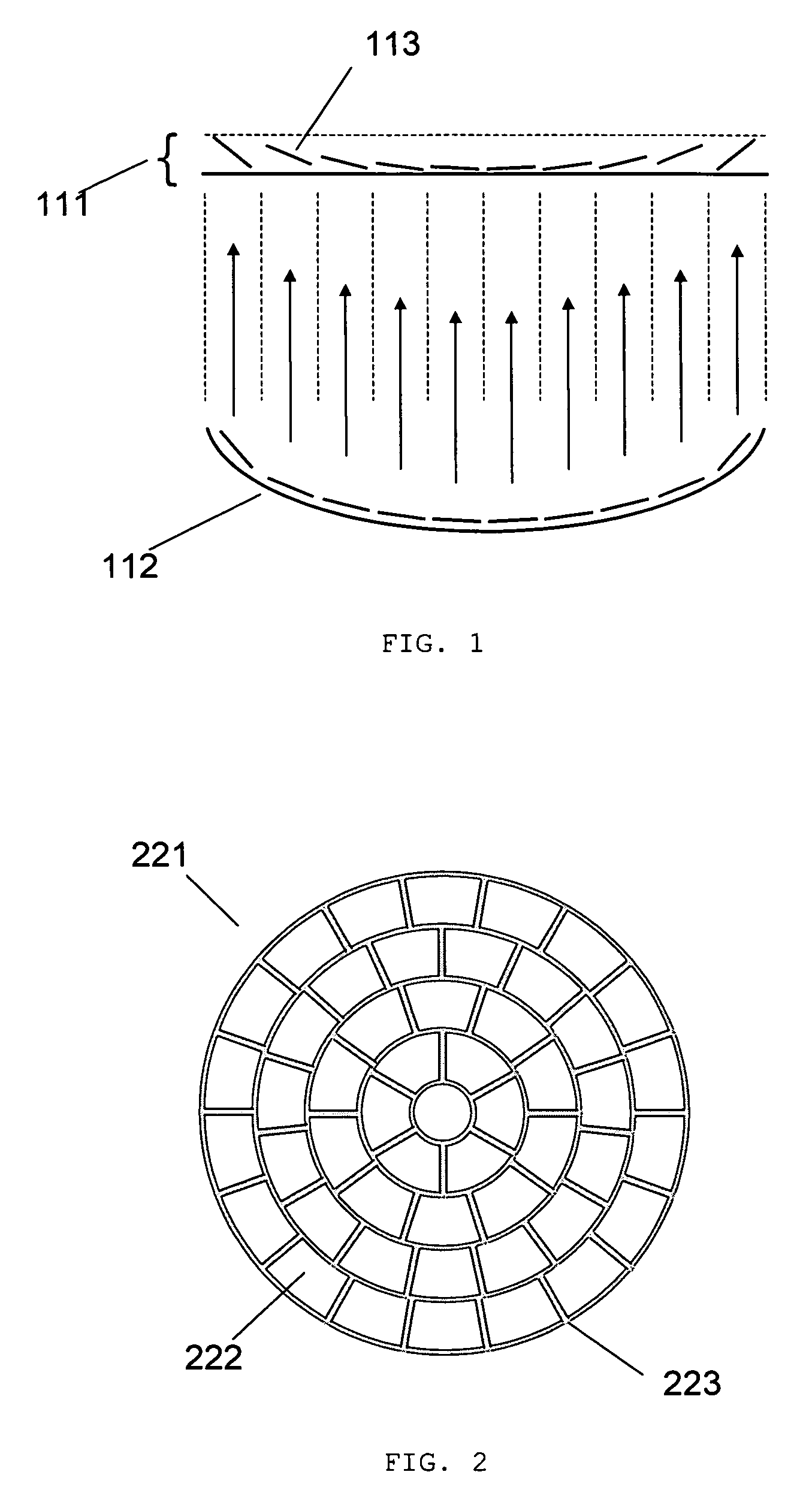
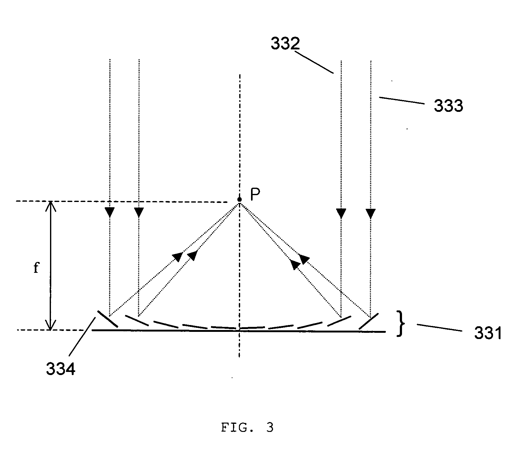
[0047] Improvements upon conventional variable focal length lenses are found in a fast-response micromirror array lens, the details of which are described in J. Boyd and G. Cho, 2003, “Fast-response Variable Focusing Micromirror Array Lens,”Proceeding of SPIE Vol. 5055: 278-286. This paper is hereby incorporated by reference. The micromirror array lens includes micromirrors and actuating component...


PUM

PropertyMeasurementUnit
movementaaaaaaaaaa
phaseaaaaaaaaaa
degree of freedomaaaaaaaaaa

Abstract

A beam focusing and scanning system using a micromirror array lens (optical system) includes a light source configured to emit light and a micromirror array lens, including at least one micromirror, optically coupled to the light source, configured to reflect the light onto a projection medium (projection plane). The optical system also includes at least one actuating component coupled to the at least one micromirror, configured to move the at least one micromirror to enable the at least one micromirror to focus the light on the projection medium. The advantages of the present invention include high speed variable focusing and scanning, large focal length variation, phase compensation, high reliability and optical efficiency, low power consumption and low cost.

Description

REFERENCE TO RELATED APPLICATIONS [0001] This application is a continuation-in-part of, and claims priority to U.S. patent application Ser. No. 10 / 855,554 (Docket No.1802.05), filed May 27, 2004, U.S. patent application Ser. No. 10 / 855,715 (Docket No.1802.06), filed May 27, 2004, U.S. patent application Ser. No. 10 / 855,287 (Docket No.1802.07), filed May 27, 2004, U.S. patent application Ser. No. 10 / 857,796 (Docket No.1802.08), filed May 28, 2004, U.S. patent application Ser. No. 10 / 857,714 (Docket No.1802.09), filed May 28, 2004, U.S. patent application Ser. No. 10 / 857,280 (Docket No.1802.10), filed May 28, 2004, U.S. patent application Ser. No. 10 / 872,241 (Docket No.1802.11), filed Jun. 18, 2004, U.S. patent application Ser. No. 10 / 893,039 (Docket No.1802.12), filed Jul. 16, 2004, U.S. patent application Ser. No. 10 / 914,474 (Docket No.1802.15), filed Aug. 9, 2004, and U.S. patent application Ser. No. 10 / 934,133 (Docket No.1802.16), filed Sep. 3, 2004, all of which are hereby incorp...

Claims


Application Information

Patent Timeline
01 Dec 2005
Publication
US20050264867A1
IPC
G02B7/32; G02B26/00; G02B26/08; G02B26/10; G02B27/40; G02F1/29
CPC
G02B5/09; G02B7/32; G02B26/0825; G02B27/40; G02B26/0841; G02B26/085; G02B26/105; G02B26/0833
Inventors
CHO, GYOUNG IL; KIM, TAE HYEON