Method and system for enabling device functions based on distance information

a technology of distance information and enabling devices, applied in the field of distance information enabling devices, can solve the problems of inconvenient transactions with fixed structure devices such as kiosks, inability of one device to transmit an electronic business card to another device located in the intended recipient's pocket or briefcase, and the inability to transmit business cards in the infrared system. to achieve the effect of enabling communication

Inactive Publication Date: 2005-12-01
NORTH STAR INNOVATIONS
View PDF15 Cites 63 Cited by
  • Summary
  • Abstract
  • Description
  • Claims
  • Application Information

AI Technical Summary

Benefits of technology

[0012] Another object of the present invention is to provide a method, system and computer program product for enabling comm

Problems solved by technology

As recognized by the present inventors, the infrared system is problematic, however, in that the infrared devices must be placed in a fixed location of close proximity and precise orientation while synchronization and data exchange takes place between the two devices.
This positioning makes transactions with fixed structure devices such as the kiosk inconvenient.
Moreover, IrDa technology requires that the data exchanging devices be within line of sight of each other making it impossible for one device to transmit an electronic business card to another device located in the intended recipients pocket or briefcase.
A deficiency observed by the present inventors is that the line-of-sight nature of infrared communication links is that it requires the user's

Method used


Image

  • Method and system for enabling device functions based on distance information
  • Method and system for enabling device functions based on distance information
  • Method and system for enabling device functions based on distance information

Examples


Embodiment Construction

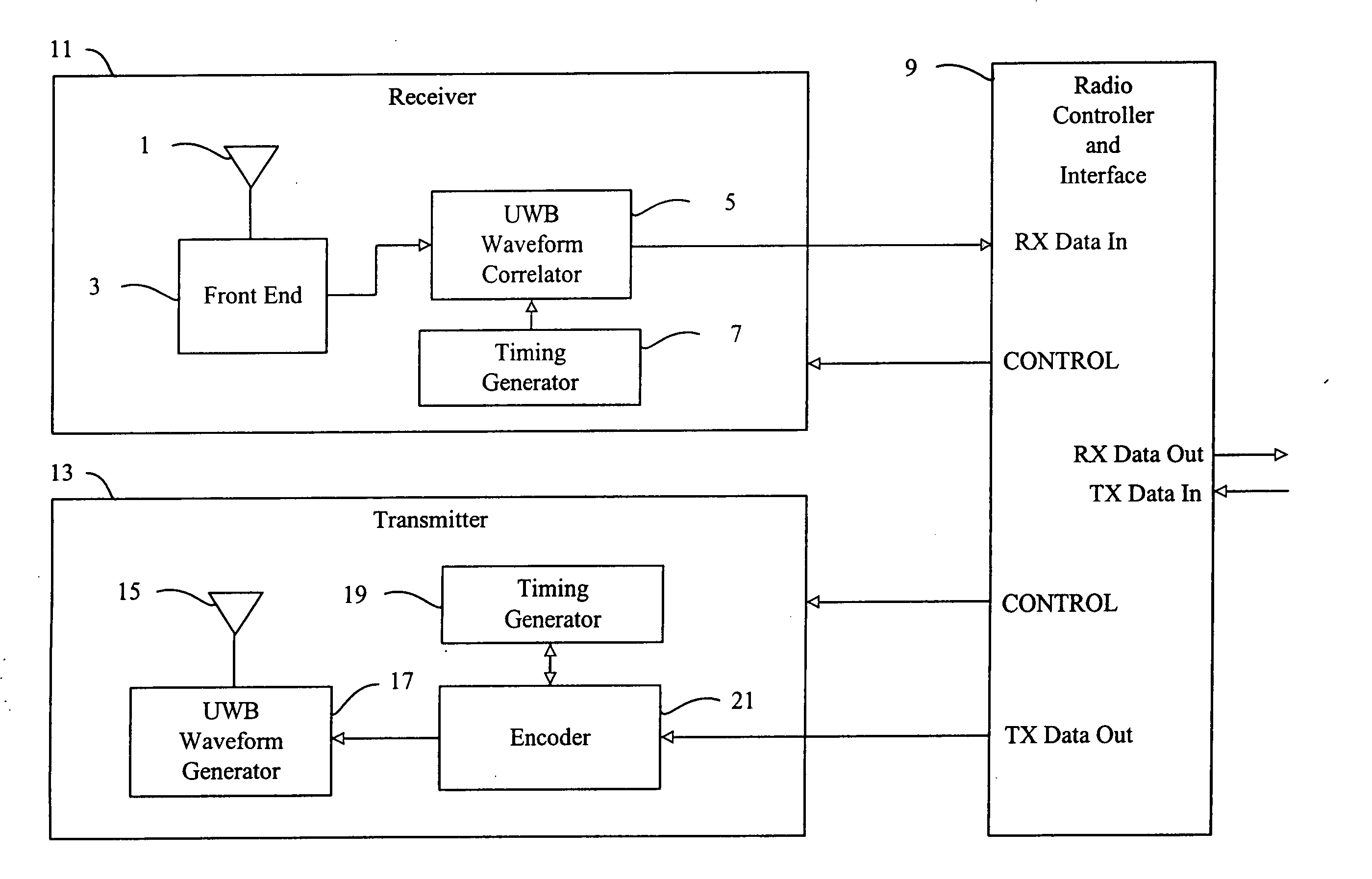
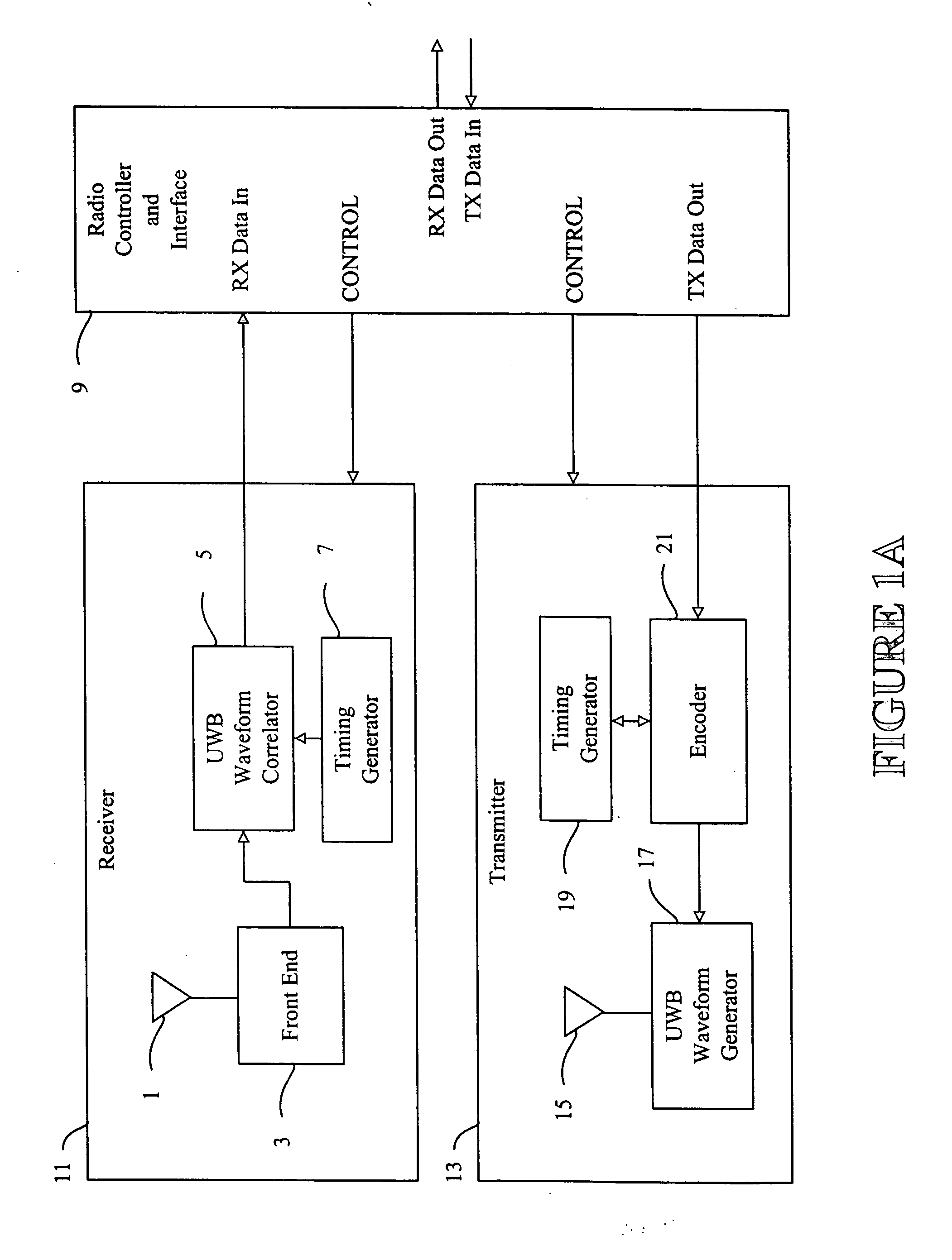
[0035] Referring now to the drawings and more particularly to FIG. 1a thereof, a block diagram of an ultra-wide band (UWB) transceiver used in accordance with the present invention is shown. In FIG. 1a, the transceiver includes three major components, namely, receiver 11, radio controller and interface 9, and transmitter 13. Alternatively, the system may be implemented as a separate receiver 11 and radio controller and interface 9, and a separate transmitter 13 and radio controller and interface 9. The radio controller and interface 9 serves as a media access control (MAC) interface between the UWB wireless communication functions implemented by the receiver 11 and transmitter 13 and applications that use the UWB communications channel for exchanging data with remote devices.

[0036] The receiver 11 includes an antenna 1 that converts a UWB electromagnetic waveform into an electrical signal (or optical signal) for subsequent processing. The UWB signal is generated with a sequence of ...


PUM


Abstract

A method, device and computer readable medium for enabling and blocking communications with a remote device based on a distance of the remote device. The method on which the device and computer readable medium are based includes transmitting a message from a local device to a remote device via an ultra wide band (UWB) wireless medium and receiving a response from the remote device via the UWB wireless medium. The transmitting and receiving steps are preferably performed in accordance with a Media Access Control (MAC) protocol. A distance between the local device and the remote device is then determined based on a time between the transmitting of the message and the receiving of the response and a function, such as communicating with the remote device, is performed in the local device based on the distance determined. The communication between the local device and the remote device may be enabled or disabled depending on the distance that the remote device is from the local device. In addition, the distance information for a remote device may be continually updated, or updated only if communication to the remote device are blocked. A positional map may be generated based on distance data determined for a plurality of reference points and the user may select the remote device from the positional map to enable communications to the positional map.

Description

CROSS-REFERENCE TO RELATED PATENT DOCUMENTS [0001] The present application is a divisional application of U.S. patent application Ser. No. 09 / 6985,202, filed Oct. 10, 2000, entitled METHOD AND SYSTEM FOR ENABLING DEVICE FUNCTIONS BASED ON DISTANCE INFORMATION, which claims benefit of priority to U.S. Provisional Application Nos. 60 / 207,225 and 60 / 217,099 filed in the United States Patent and Trademark Office on May 26, 2000, and Jul. 10, 2000, respectively. [0002] The present document contains subject matter related to that disclosed in commonly owned, co-pending application Ser. No. 09 / 209,460 filed Dec. 11, 1998, entitled ULTRA WIDE BANDWIDTH SPREAD-SPECTRUM COMMUNICATIONS SYSTEM (Attorney Docket No. 10188-0001-8); Ser. No. 09 / 633,815 filed Aug. 7, 2000, entitled ELECTRICALLY SMALL PLANAR UWB ANTENNA (Attorney Docket No. 10188-0005-8); application Ser. No. 09 / 563,292, filed May 3, 2000, entitled PLANAR ULTRA WIDE BAND ANTENNA WITH INTEGRATED ELECTRONICS (Attorney Docket No. 10188-...

Claims


Application Information

Patent Timeline
IPC IPC(8): G01S13/02H04B1/7163H04J3/06H04L12/28H04L12/56H04L25/49H04L27/00H04W24/00H04W28/18H04W74/00H04W80/02
CPCG01S7/023G01S13/0209H04B1/7163H04J3/0682H04L25/4902H04W80/02H04L63/0492H04W24/00H04W28/18H04W74/00H04L27/0004H04W12/63
Inventor ROFHEART, MARTINMCCORKLE, JOHN W.
Owner NORTH STAR INNOVATIONS
Why Eureka
Try Eureka