Method of image feature coding and method of image search

a technology of image feature and image search, applied in the field of image feature coding and image search, can solve the problems of difficult search for moving images, image search system where, and network cannot be buil

Inactive Publication Date: 2005-12-01
MITSUBISHI ELECTRIC CORP
View PDF14 Cites 18 Cited by
  • Summary
  • Abstract
  • Description
  • Claims
  • Application Information

AI Technical Summary

Benefits of technology

[0015] Accordingly, a general object of the present invention is to provide a method of imag...

Problems solved by technology

Since the target of the image search system described above is the still image 201, there is a drawback in that it is difficult to search for moving images.
Therefore, acco...

Method used


Image

  • Method of image feature coding and method of image search
  • Method of image feature coding and method of image search
  • Method of image feature coding and method of image search

Examples


first embodiment

[0054] According to an apparatus of a first embodiment, a rectangular area surrounding an object contained in a frame of a video sequence is identified as a segment. Segments are extracted from each frame constituting a video signal. A feature stream identifying the features of the segments is generated.

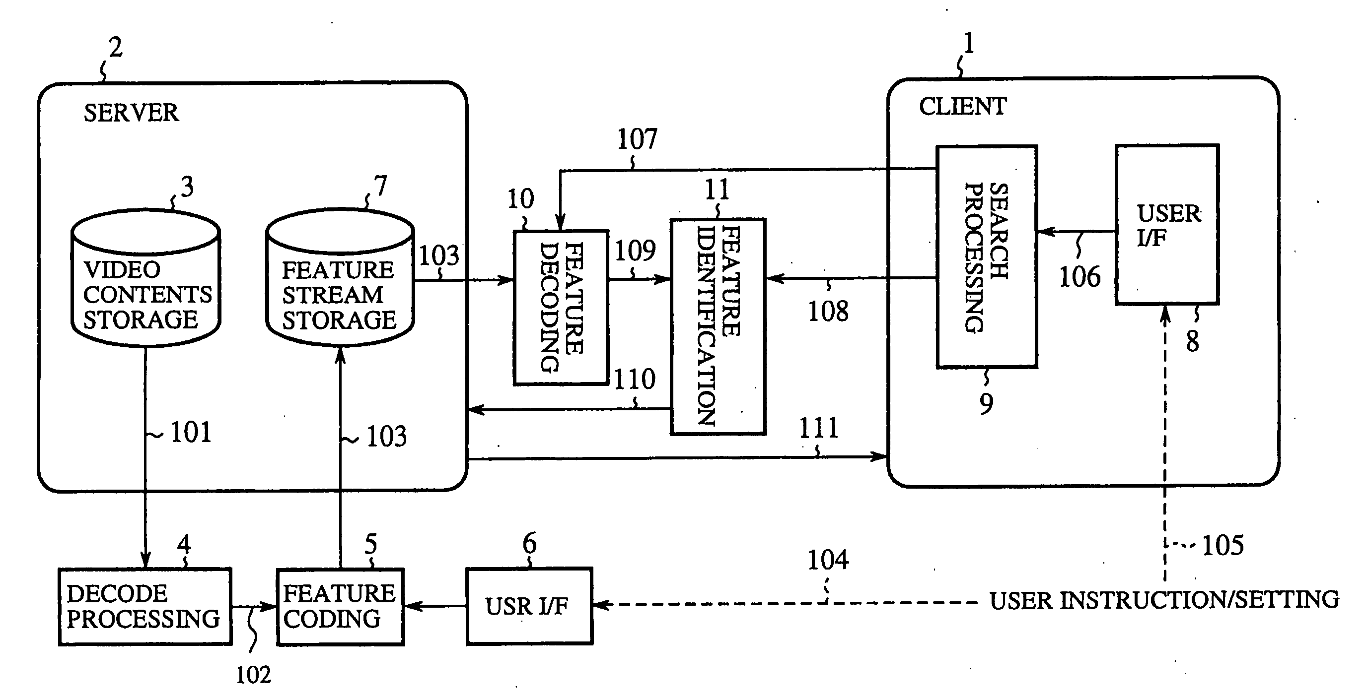
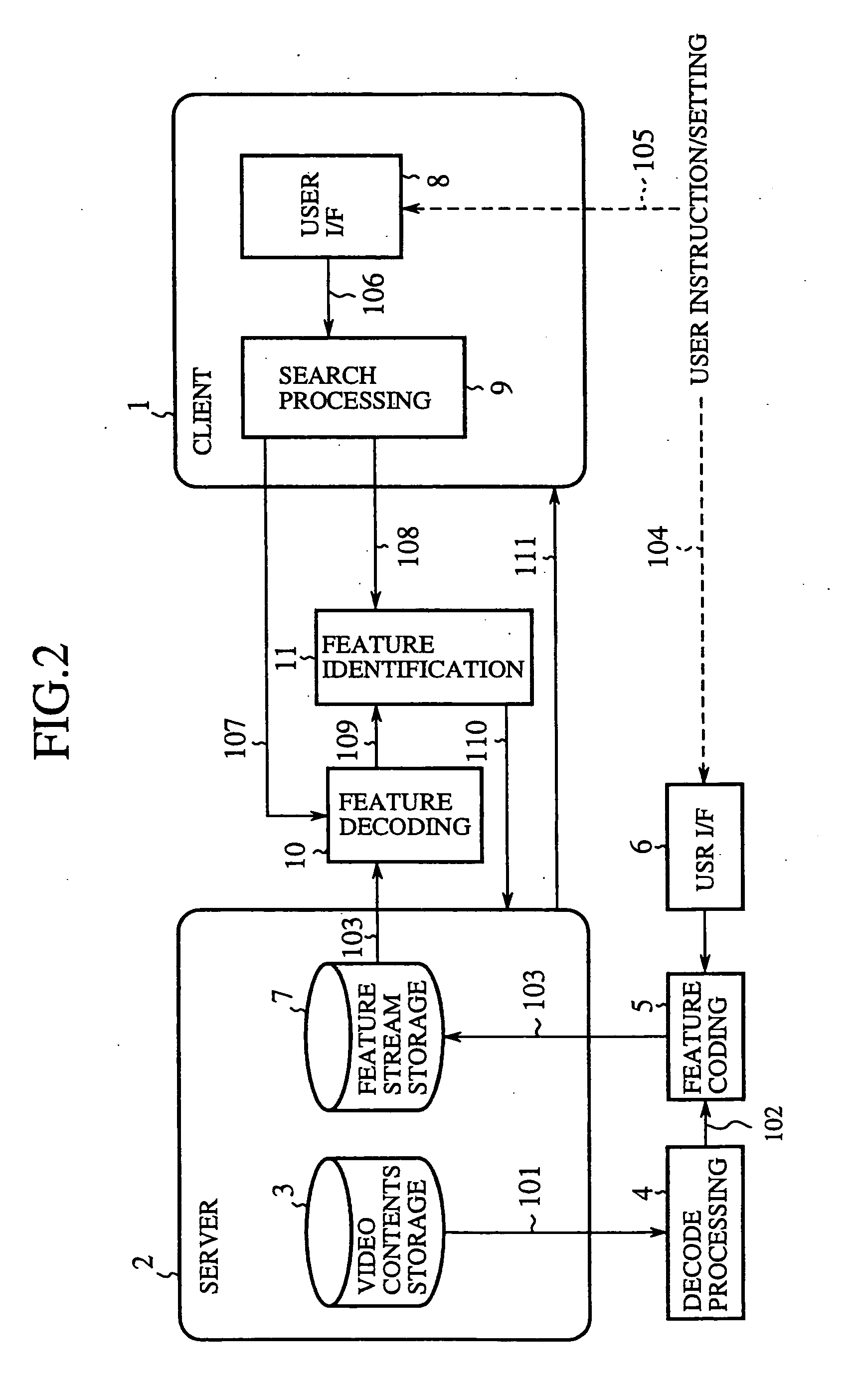
[0055] A description will now be given of a system using the apparatus of the first embodiment. FIG. 2 is a block diagram showing a construction of the typical system. Referring to FIG. 2, the system comprises a client 1, a server 2, a video contents storage unit 3 for storing video contents 111, a decode processing unit 4 for decoding a digitally-compressed bit stream 101 in the video content 111 stored in the video contents storage unit 3 so as to output a video signal 102.

[0056] Referring to FIG. 2, the system further comprises a feature coding unit 5 for receiving the video signal 102 produced as a result of decoding by the decode processing unit 4, and generating a feature str...

second embodiment

[0123]FIG. 14 is a block diagram showing an internal construction of the segment extracting unit 23 according to a second embodiment of the present invention. The segment extracting unit 23 comprises a segment extraction processing unit 61 for extracting segment data 161 from the key frame image 123; a segment identification processing unit 62 for checking segments from the key frame image against segments from the existing key frame image 123 stored in the a reference image memory 63 for a match so as to give identification to the segments.

[0124] In this example, segments from one key frame are checked against segments in other key frames. The segments are associated with objects in the video content. That is, the key frame is not considered as a closed domain as far as the segments therein are concerned. Segments are extracted as image areas in which the objects constituting the video content 111 are captured from moment to moment.

[0125] When the segment extraction processing un...

third embodiment

[0132]FIG. 16 is a block diagram showing an internal construction of the segment extracting unit 23 according to a third embodiment. Referring to FIG. 16, the segment extracting unit 23 comprises a segment tracking processing unit 71 for receiving the key frame image 123 and referring to the reference image memory 63, so as to output the segment number 126, the intra-segment image sample value 151, the segment horizontal and vertical sizes 152 and movement information 171. The representative color assigning unit 52 and the size computing unit 53 are the same as the corresponding units of FIG. 14.

[0133] In this example, the segment is obtained as an image area found in the key frame as a result of tracking an object in the video content 111. Object tracking is performed by the segment tracking processing unit 71.

[0134] Various approaches for object tracing are proposed. Selection of one of these approaches is the not subject matter of the present invention. By using an appropriate ...


PUM


Abstract

A feature coding unit extracts and encodes a feature of a video signal so as to generate a feature stream. A feature identifying unit checks a decoded feature obtained as a result of decoding the feature stream against a search key from a user for a match so that a video content requested by the user is retrieved.

Description

CROSS-REFERENCE TO THE RELATED APPLICATION [0001] This Application is a continuation of International Application No. PCT / JP99 / 00403, whose International filing date is Jan. 29, 1999, the disclosures of which Application are incorporated by reference herein.BACKGROUND OF THE INVENTION [0002] 1. Field of the Invention [0003] The present invention generally relates to methods of image feature coding and image search and, more particularly, to a method of image feature coding and a method of image search in which features of analog or digital data of moving images or still images are extracted and coded so that the image data is searched using the coded feature. [0004] 2. Description of the Related Art [0005]FIG. 1 is a block diagram showing a related-art image search system described in Denshi Jouhou Tsuushin Gakkai Rombunshi D-II Vol. 79-D-II No. 4, April, 1996, pp. 476-483. Referring to FIG. 1, the system comprises a pre-processing unit 91 for segmenting a still image 201, attaching...

Claims


Application Information

Patent Timeline
IPC IPC(8): H04N19/00G06F17/30G06K9/00G06T7/20G11B27/10G11B27/28H04N5/45H04N7/24H04N19/20H04N19/21H04N19/51H04N19/513H04N19/90
CPCG06F17/3025H04N19/20G06F17/3079G06F17/30802G06F17/30805G06F17/30811G06F17/30817G06K9/00711G06T7/20G11B27/107G11B27/28G11B2220/41G11B2220/90H04N5/45H04N7/24G06T9/001H04N19/46G06F17/30256H04N21/232H04N21/23412H04N21/23418H04N21/234345H04N21/234363H04N21/23614H04N21/26603H04N21/4348H04N21/4828G06F16/78G06F16/5838G06F16/7854G06F16/786G06F16/7837G06F16/785G06V20/40G06T7/00G06F16/5854
Inventor SEKIGUCHI, SHUNICHIYAMADA, YOSHIHISACHOW, JAMESASAI, KOHTARO
Owner MITSUBISHI ELECTRIC CORP
Why Eureka
Try Eureka