Remote passenger control unit and method for using the same

a passenger control and remote control technology, applied in the direction of aircraft crew accommodation, wing accessories, television systems, etc., can solve the problems of additional wiring, cumbersome and inefficient arrangement of aircraft in limited space environments, and extra pounds of wire cost in fuel and aircraft carrying capacity, so as to eliminate extra wiring

Inactive Publication Date: 2005-12-01
THALES AVIONICS INC
View PDF10 Cites 92 Cited by
  • Summary
  • Abstract
  • Description
  • Claims
  • Application Information

AI Technical Summary

Benefits of technology

[0014] The embodiments of the present invention described herein permit display / computing equipment and control devices to be physically connected to the closest SEB without regard to the passenger to be serviced by the device by employing networking protocol techniques in or for use with the SEBs. The basic communications network is used as a pathway for passenger control device packets to tunnel from the remote control device to the computer under control, thus eliminating extra wiring and enabling the control devices to be “physical location independent”.

Problems solved by technology

However, this type of arrangement can prove cumbersome and inefficient in limited-space environments such as passenger vehicles.
However, additional wiring has several important disadvantages.
For example, in weight sensitive applications such as in-flight entertainment, extra pounds of wire cost in both fuel and aircraft carrying capacity.
Also, extra wiring that is potentially exposed as it passes from seat 10 to seat 10 is especially vulnerable to physical damage and thus lowers system reliability.
Furthermore, the complexity of this additional wiring makes maintenance functions and reconfiguration functions more complex and time-consuming.
In addition, the ability to provide alternate control in the event of a control device or wiring failure is very limited due to the required physical interconnection.
However, smaller wires are more difficult to repair and in most cases, if the wires are smaller than 24 AWG, they typically cannot be repaired and entire cable harnesses must be replaced, which results in a significant extra cost.
Extra protection and careful routing can minimize the potential for wire damage, but the protective materials generally creates heavier and longer interconnect wiring and the rerouting of cables makes the wiring much more difficult and time consuming to install.
Also, special tools and additional training can help reduce the time required for maintenance and reconfiguration, but impose additional costs to operators of the systems.
Although these conventional solutions may be somewhat suitable for solving the disadvantages associated with wiring techniques, they introduce their own disadvantages and problems as discussed above.
Furthermore, as can be appreciated from FIG. 6, these wiring techniques do not improve the ability to connect other control devices, such as keyboards, pointing devices, joysticks trackballs and so on, to a display / computing equipment 20.

Method used


Image

  • Remote passenger control unit and method for using the same
  • Remote passenger control unit and method for using the same
  • Remote passenger control unit and method for using the same

Examples


Embodiment Construction

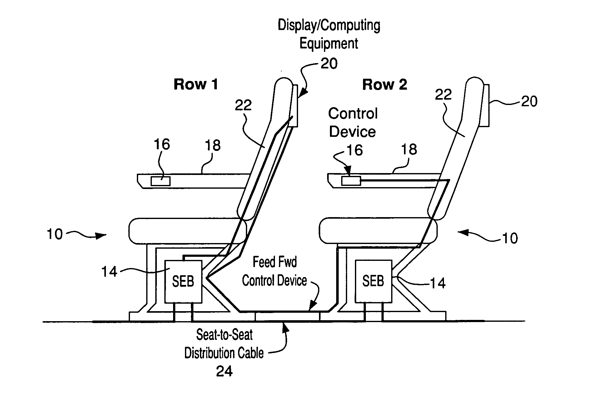
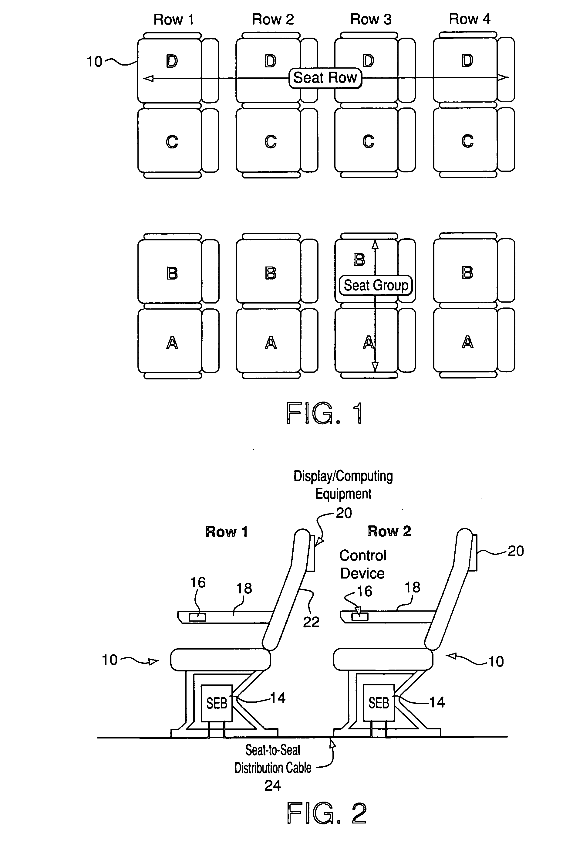
[0031] A seat group arrangement employing a system and method for interconnecting seat equipment according to an embodiment of the present invention is shown conceptually in FIG. 7. As with the arrangement shown in FIG. 2 as discussed above, each seat group includes an under-seat SEB 14. A passenger control unit (PCU) for each seat 10 includes a control device 16 that is typically mounted on the arm 18 of the passenger seat 10 for convenience, and can be fixed in place or tethered for ease of use. The display / computing equipment 20 for a seat 10, for example, in a seat group of Row 2 is typically mounted to the rear of the seat back 22 of a seat 10 in a seat group of Row 1 directly in front of that seat 10 as shown in FIG. 2.

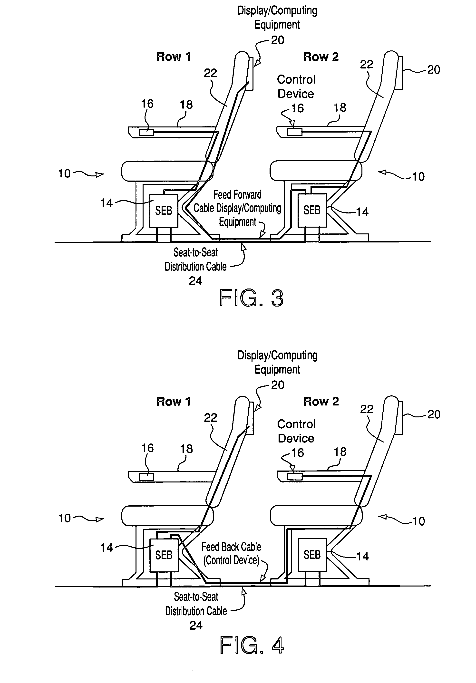
[0032] Unlike the conventional arrangements shown in FIGS. 3 through 5 as discussed above, the system shown in FIG. 7 does not require that wires be deployed to physically and directly connect the control devices 16 to a respective display / computing equipment 2...


PUM


Abstract

A system and method for connecting control devices for display and computing equipment of in-flight entertainment systems (IFESs) in a physical location independent manner in environments where the control devices cannot be co-located and directly connected to the display/computing equipment, such as on an aircraft or other vehicle having space restrictions. More particularly, the present invention relates to a system and method for enabling the use of improved passenger control units (PCU) including control devices such as pointing devices, keyboards, joysticks, and game controllers, and so on, with interactive in-flight entertainment systems.

Description

CROSS-REFERENCE TO RELATED PATENT APPLICATIONS [0001] This application claims benefit under 35 U.S.C. § 119(e) from U.S. Provisional Patent Application No. 60 / 545,305, filed Feb. 17, 2004, and from U.S. Provisional Patent Application No. 60 / 545,062, filed Feb. 17, 2004, the entire content of each being incorporated herein by reference.BACKGROUND OF THE INVENTION [0002] 1. Field of the Invention [0003] The present invention relates to control devices for display and computing equipment for use in environments where the control devices cannot be co-located and directly connected to the display / computing equipment, such as on an aircraft or other vehicle having space restrictions. More particularly, the present invention relates to improved passenger control units (PCU) including control devices such as pointing devices, keyboards, joysticks, and game controllers, and so on, for use with interactive in-flight entertainment systems. [0004] 2. Description of the Related Art [0005] Many v...

Claims


Application Information

Patent Timeline
Patent Type & Authority Applications(United States)
IPC IPC(8): B60N2/48B60N2/75B64D11/00E05F15/00
CPCB60N2/4693B64D11/0624B64D11/0015B60N2/4876B60N2/797B64D11/00155
Inventor BRADY, KENNETH A. JR.
Owner THALES AVIONICS INC
Why Eureka
Try Eureka