Unlock instant, AI-driven research and patent intelligence for your innovation.
Terminal for guideway transit system
Inactive Publication Date: 2005-12-08
PARK TAEJIN
View PDF4 Cites 3 Cited by
Summary
Abstract
Description
Claims
Application Information
AI Technical Summary
This helps you quickly interpret patents by identifying the three key elements:
Problems solved by technology
Method used
Benefits of technology
Benefits of technology
[0010] The present invention has been made in order to solve the above problems, and it is, therefore, an object of the present invention to reduce the size of the terminal by parking the vehicles on the external parking section through the external entry, and to allow the dual-mode vehicle entering from the outside road to use the guideway through the terminal.
[0047] Namely, in case of many passengers, the vehicle 60 that has finished entering of the passengers, proceeds toward the front side of the entry 10, and the passengers enter the following vehicle 60 at the berth 21 even during departure-standby time for waiting for a departure signal, thus the time for the passengers to enter the vehicle is shortened.
Problems solved by technology
Since a current transit system for multi passengers serviced on the basis of an on-time system such as the general subway and the light rail transit, etc. causes traffic congestion and is operated in such a manner as to stop at every station, there has been a problem in that it takes much time to their destination.
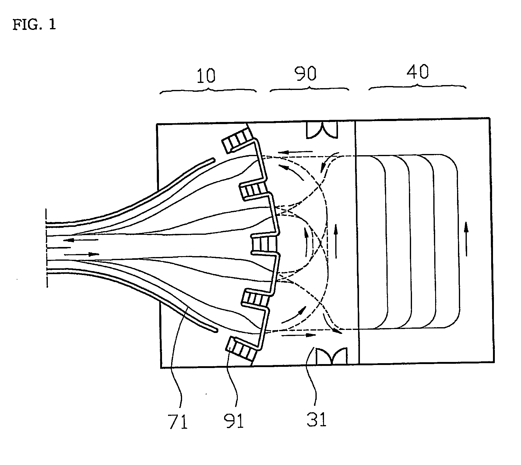
The terminal of such system, however, requires a large parking space in order to park numerous vehicles needed for the high-frequency service, and allows a passenger to go up and down a stairway 91 to alight from and ride in a vehicle, so that he or she suffers from an inconvenient during the use.
Also, there always exists a risk of head-on collision of vehicles, for the direction where vehicle proceeds to a berth from a U-turn section 90 is opposite to the direction where the vehicle proceeds to a parking lot from the U-turn section 90.
Also, the above system is problematic in that the dual-mode vehicle that possibly operates on both the guideway where pilot lines are formed and the general road cannot use the guideway through the entry.
Method used
Image
Click on the blue label to locate the original text in one second.
Reading with bidirectional positioning of images and text.
Examples
embodiment 1
Construction 1 of a Terminal for a Guideway Transit
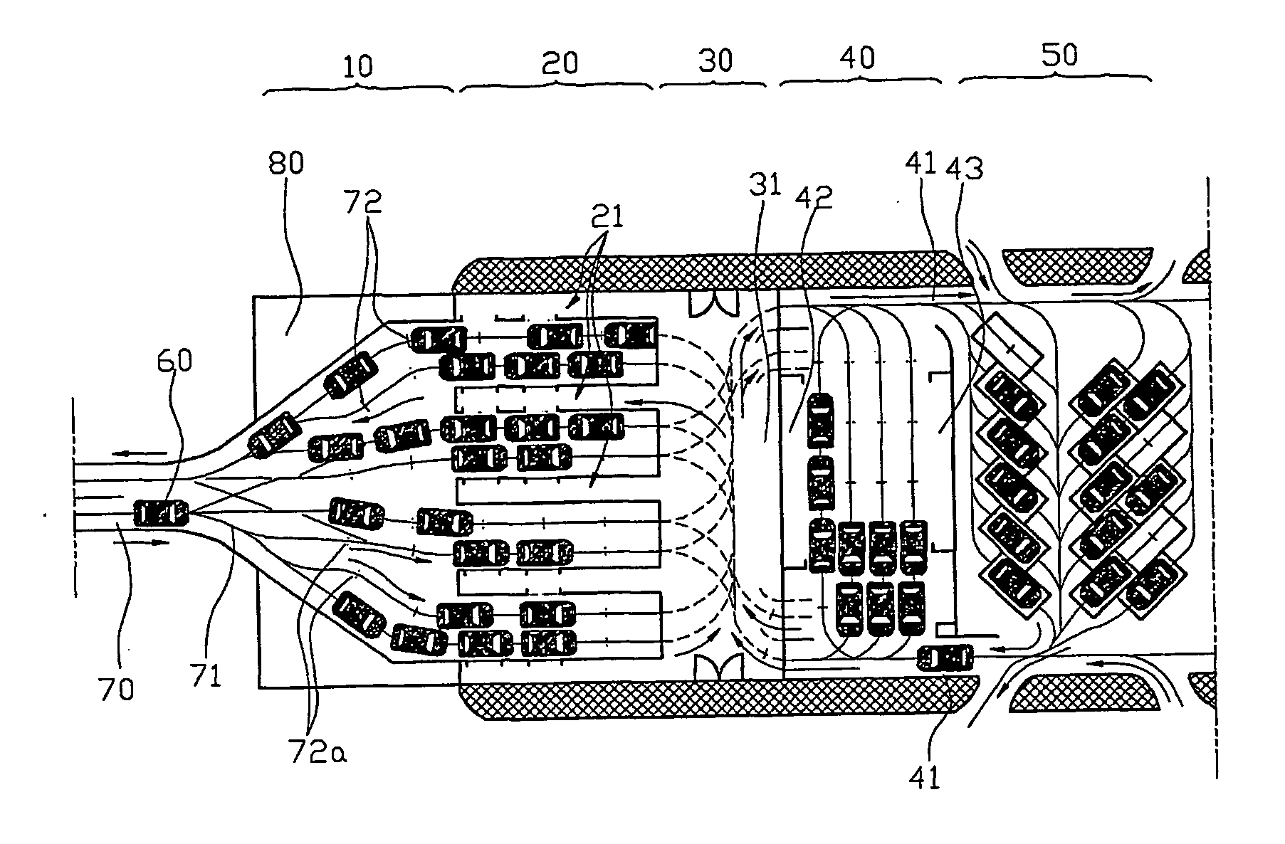
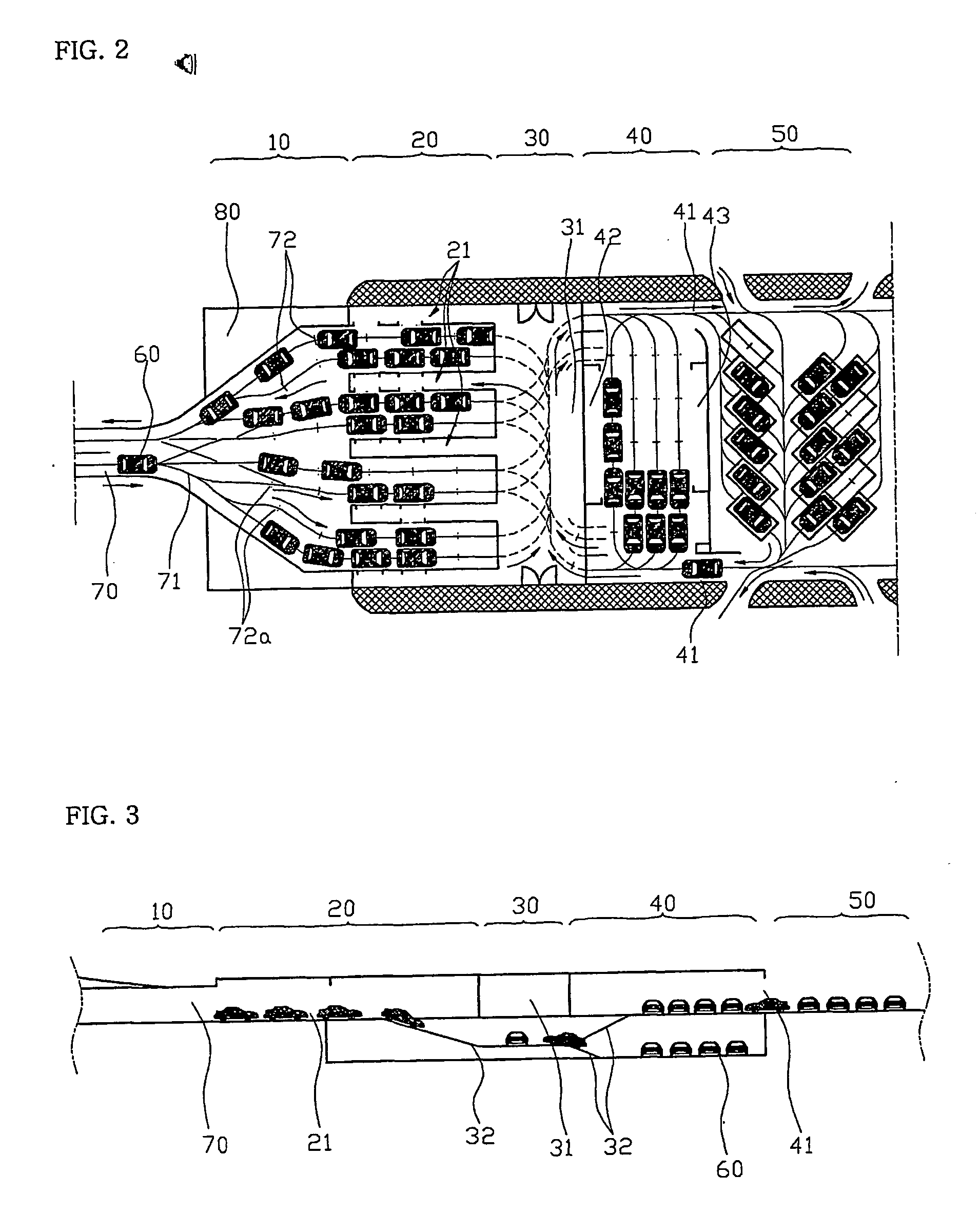
[0053] An entry section 10 is formed on the end of the guideway 70 on which a vehicle 60 moves one by one in both directions.
[0054] As shown in FIG. 2, the entry section 10 is configured in such a manner that each of the pilot lines 71 is divided into four branches.
[0055] At this time, in FIG. 2, the third pilot line 71 from the top is connected to a pilot line 71 oriented toward the entering direction of the guideway 70, and the sixth pilot line 71 is connected to a pilot line 71 oriented toward the outgoing direction of the guideway 70. With such a connections, the vehicle 60 entering from the entry road can enter the terminal using six branches at the maximum.
[0056] Namely, in the case where there is increased the number of the entering vehicles 60, the pilot line 71 oriented toward the entering direction is changed into six in number and the pilot line 71 oriented toward the outgoing direction becomes two in number. On the c...
embodiment 2
Construction 2 of a Terminal for a Guideway Transit
[0067] In the terminal of the first embodiment, the pilot lines connected to one berth 21 are formed with an interval of 2 m maintained over a length of 10 m so that the vehicles 60 can stop side by side at the end of the berth 21.
[0068] Namely, there is provided a terminal for the guideway transit wherein in the case where the number of entering vehicles increases, more vehicles can stand by for alighting at the entry section 10.
embodiment 3
Construction 3 of a Terminal for a Guideway Transit
[0069] In the terminal of the first embodiment, the standby line 72 for indicating a stopping position of the vehicle 60 is formed at necessary points of the pilot lines 71 and such standby lines 72 are also formed at the entering / alighting section 20 and the entry section 10, so that the vehicle 60 that has finished entering of the passengers at the berth 21, proceeds up to the standby line 72 formed at the entry section 10, and stands by for departure.
[0070] By such a configuration, there is provided a terminal for the guideway transit, wherein in case of many passengers, the vehicle 60 that has finished entering of the passengers, proceeds up to the standby line 72 at the front side of the entry 10 so that the passengers enter the following vehicle 60 at the berth 21 even during departure-standby time for waiting for a departure signal, thereby shortening the time for the passengers to enter the vehicle.
[0071] The operations o...
PUM
Abstract
A terminal for the guideway transit includes: an entry section at which a plurality of pilot lines of the guideway is divided into branches; an entering / alighting section for allowing passengers to enter into / from a vehicle after the vehicle moves to the entering / alighting section along the pilot lines and stops at the entering / alighting section; a U-turn section for allowing the vehicle at the entering / alighting section to perform U-turn; and a parking section connected at one side to the U-turn section and having an external entry formed at the other side. The dual-mode vehicle that possibly operates on the general road and the guideway can enter the guideway through the external entry of the terminal, and most vehicles used in high-frequency service in a high carry capacity, can be parked at the parking lot in the outside through the external entry, greatly reducing the size of the terminal.
Description
TECHNICAL FIELD [0001] The present invention relates to a terminal for a guideway transit system. The terminal for guideway transit of the present invention can reduce the size of the terminal by parking numerous vehicles for use in high-frequency service at an external parking space or other floor using an external entry or a ramp instead of a large terminal. [0002] Also, the dual-mode vehicles remodeled from the private cars or the taxies, for possibly operating on a guideway, can use the guideway by entering it through the external entry of this terminal. BACKGROUND ART [0003] Since a current transit system for multi passengers serviced on the basis of an on-time system such as the general subway and the light rail transit, etc. causes traffic congestion and is operated in such a manner as to stop at every station, there has been a problem in that it takes much time to their destination. [0004] In order to solve such a problem, the applicant of the present invention has proposed ...
Claims
Application Information
Patent Timeline
Application Date:The date an application was filed.
Publication Date:The date a patent or application was officially published.
First Publication Date:The earliest publication date of a patent with the same application number.
Issue Date:Publication date of the patent grant document.
PCT Entry Date:The Entry date of PCT National Phase.
Estimated Expiry Date:The statutory expiry date of a patent right according to the Patent Law, and it is the longest term of protection that the patent right can achieve without the termination of the patent right due to other reasons(Term extension factor has been taken into account ).
Invalid Date:Actual expiry date is based on effective date or publication date of legal transaction data of invalid patent.

