Diesel-electric locomotive engine waste heat recovery system

a technology of waste heat recovery and diesel-electric locomotives, which is applied in the direction of locomotives, machines/engines, lighting and heating apparatus, etc., can solve the problems of limited use of thermoelectric technology, and achieve the effect of recovering waste hea

Inactive Publication Date: 2005-12-08
ELECTRO-MOTIVE DIESEL
View PDF2 Cites 39 Cited by
  • Summary
  • Abstract
  • Description
  • Claims
  • Application Information

AI Technical Summary

Benefits of technology

[0009] The present invention is a system which recovers waste heat generated by a locomotive diesel engine by utilization of a thermoelectric device connected to a source of waste heat of the engine to thereby convert this waste heat into additional electricity or other useful work (as, for example, air conditioning) to the locomotive.

Problems solved by technology

Historically, due to its low cooling coefficient of performance and energy conversion efficiency, thermoelectric technology has seen limited use.

Method used


Image

  • Diesel-electric locomotive engine waste heat recovery system
  • Diesel-electric locomotive engine waste heat recovery system
  • Diesel-electric locomotive engine waste heat recovery system

Examples


Embodiment Construction

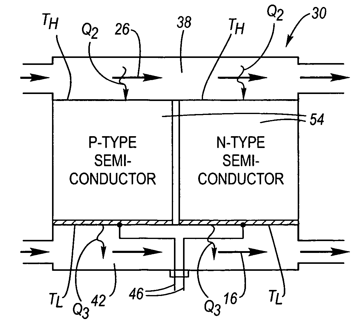
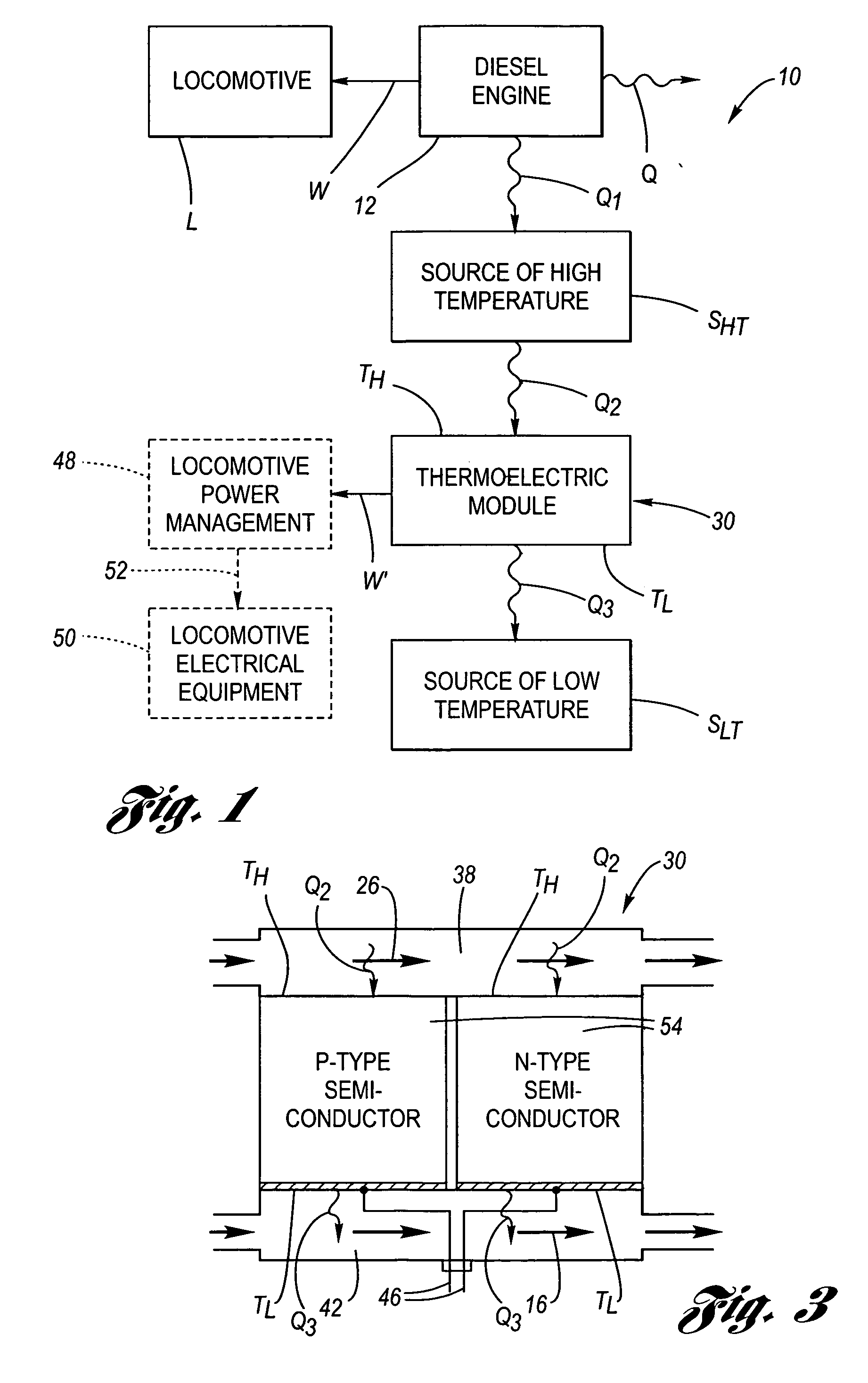
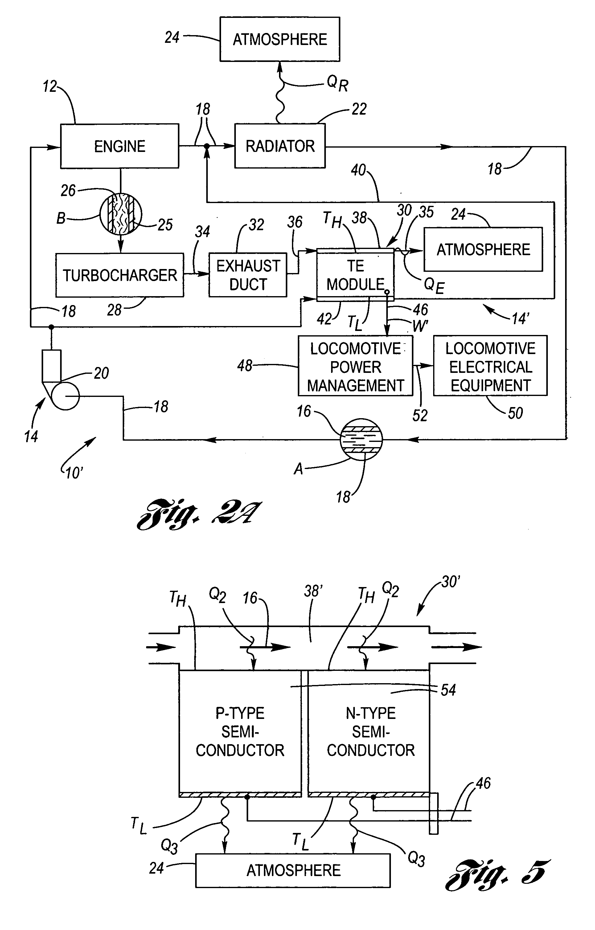
[0022] Referring now to the drawings, wherein in the various views like numbers refer to like functioning components, FIG. 1 depicts a flow chart schematic of a locomotive diesel engine waste heat recovery system 10. The diesel engine 12 combusts fuel and produces work W for powering the locomotive L and also produces waste heat. A portion of the waste heat Q is dumped to the atmosphere, and another portion of the waste heat Q1 provides a source of high temperature SHT. The heat from the source of high temperature SHT is exposed to one side of a thermoelectric module 30 and supplies heat Q2 thereto so as to provide a high temperature heat source TH thereat. A source of low temperature SLT, as for example engine coolant or the atmosphere itself, is in contact with an opposite side of the thermoelectric module and extracts heat Q3 so as to provide a low temperature heat source TL thereat. The high temperature heat source TH has a higher temperature than that of the low temperature hea...


PUM


Abstract

A locomotive diesel engine waste heat recovery system for converting waste heat of engine combustion into useful work. A thermoelectric module is connected to the hot engine exhaust to provide a high temperature heat source, and the engine coolant system is also connected to the thermoelectric module to provide a low temperature heat source. The difference in temperature of the heat sources powers the thermoelectric module to convert waste heat of the engine into electricity to power selected devices of the locomotive.

Description

CROSS-REFERENCE TO RELATED APPLICATIONS [0001] The present patent application claims the benefit of provisional patent application Ser. No. 60 / 577,966, filed on Jun. 8, 2004.TECHNICAL FIELD [0002] The present invention relates to diesel-electric locomotives, and more particularly to a locomotive waste energy recovery system including a thermoelectric device. BACKGROUND OF THE INVENTION [0003] In most modern railroad diesel-electric locomotives, the diesel engine drives an electric generator which in turn provides electrical power to motors which are mechanically geared to the locomotive wheels. The diesel engine is typically turbocharged. The turbocharger provides charge air for the diesel engine fuel combustion. In this regard, combustion exhaust gas provides work of expansion across a turbine section of the turbocharger which, in turn, provides rotational energy to the compressor section of the turbocharger so as to produce the charge air for combustion. The exhaust gas from the t...

Claims


Application Information

Patent Timeline
Patent Type & Authority Applications(United States)
IPC IPC(8): B61C7/00F01N5/02F02G5/00F02G5/02F25B21/02H01L35/28H01L35/30
CPCF01N5/025F02G5/02Y02T10/166H01L35/30Y02T10/16F02G2260/00Y02P80/15Y02T10/12H10N10/13
Inventor MEYERKORD, DANIEL J.GODING, DAVID J.
Owner ELECTRO-MOTIVE DIESEL
Why Eureka
Try Eureka