Elevator supervision

a technology for elevators and safety chains, applied in elevators, building lifts, transportation and packaging, etc., can solve the problems of partial redundancy in the collection of information within existing elevator installations, limited functionality of the elevator safety chain sensor, and relatively old “tried and trusted” mechanical or electromechanical principles, etc., to achieve easy detection of deviations, increase functionality, and initiate a safe reaction

Active Publication Date: 2005-12-08
INVENTIO AG
View PDF8 Cites 51 Cited by
  • Summary
  • Abstract
  • Description
  • Claims
  • Application Information

AI Technical Summary

Benefits of technology

[0007] Furthermore, since the two independent sensor systems monitor different parameters, there is an increased functionality; for example the method an

Problems solved by technology

Accordingly, while the sensor technology used to supply the controller with information has improved dramatically over recent years, the sensors used in elevator safety chains are still based on relatively old “tried and trusted” mechanical or electromechanical principles with very restricted functionality.
Since the controller and the safety chain systems independently gather the same information to a certain extent, there has always been a partial redundancy in the collection of information within e

Method used


Image

  • Elevator supervision
  • Elevator supervision
  • Elevator supervision

Examples


first embodiment

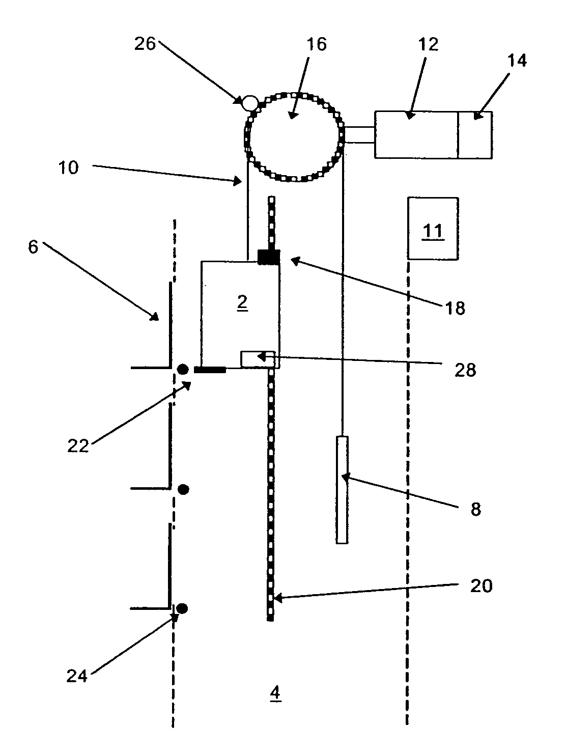
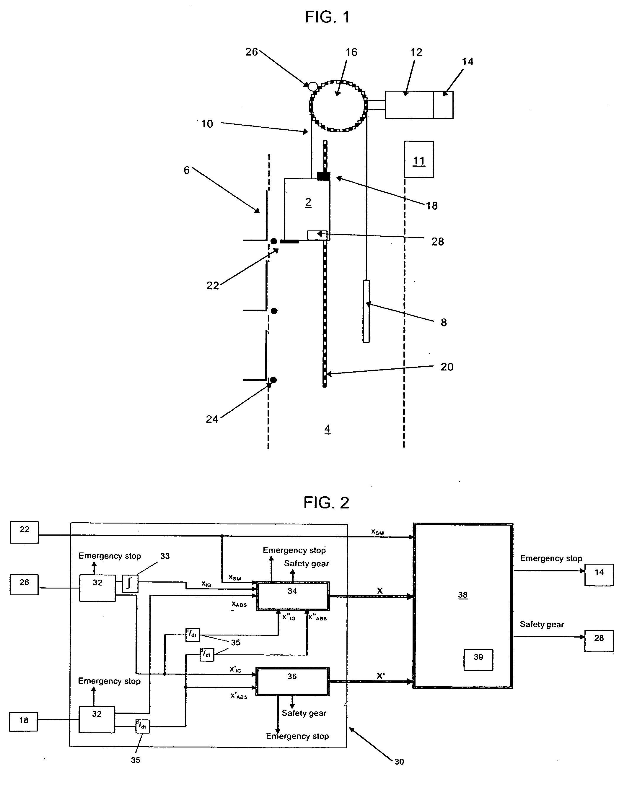
[0020]FIG. 1 illustrates an elevator installation according to the invention. The installation comprises a car 2 movable vertically along guide rails (not shown) arranged within a hoistway 4. The car 2 is interconnected with a counterweight 8 by a rope or belt 10 which is supported and driven by a traction sheave 16 mounted on an output shaft of a motor 12. The motor 12 and thereby the movement of the car 4 is controlled by an elevator controller 11. Passengers are delivered to their desired floors through landing doors 6 installed at regular intervals along the hoistway 4. The traction sheave 16, the motor 12 and the controller 11 can be mounted in a separate machine room located above the hoistway 4 or alternatively within an upper region of the hoistway 4.

[0021] As with any conventional installation, the position of the car 4 within the shaft 4 is of vital importance to the controller 11. For that purpose, equipment for producing shaft information is necessary. In the present exa...

second embodiment

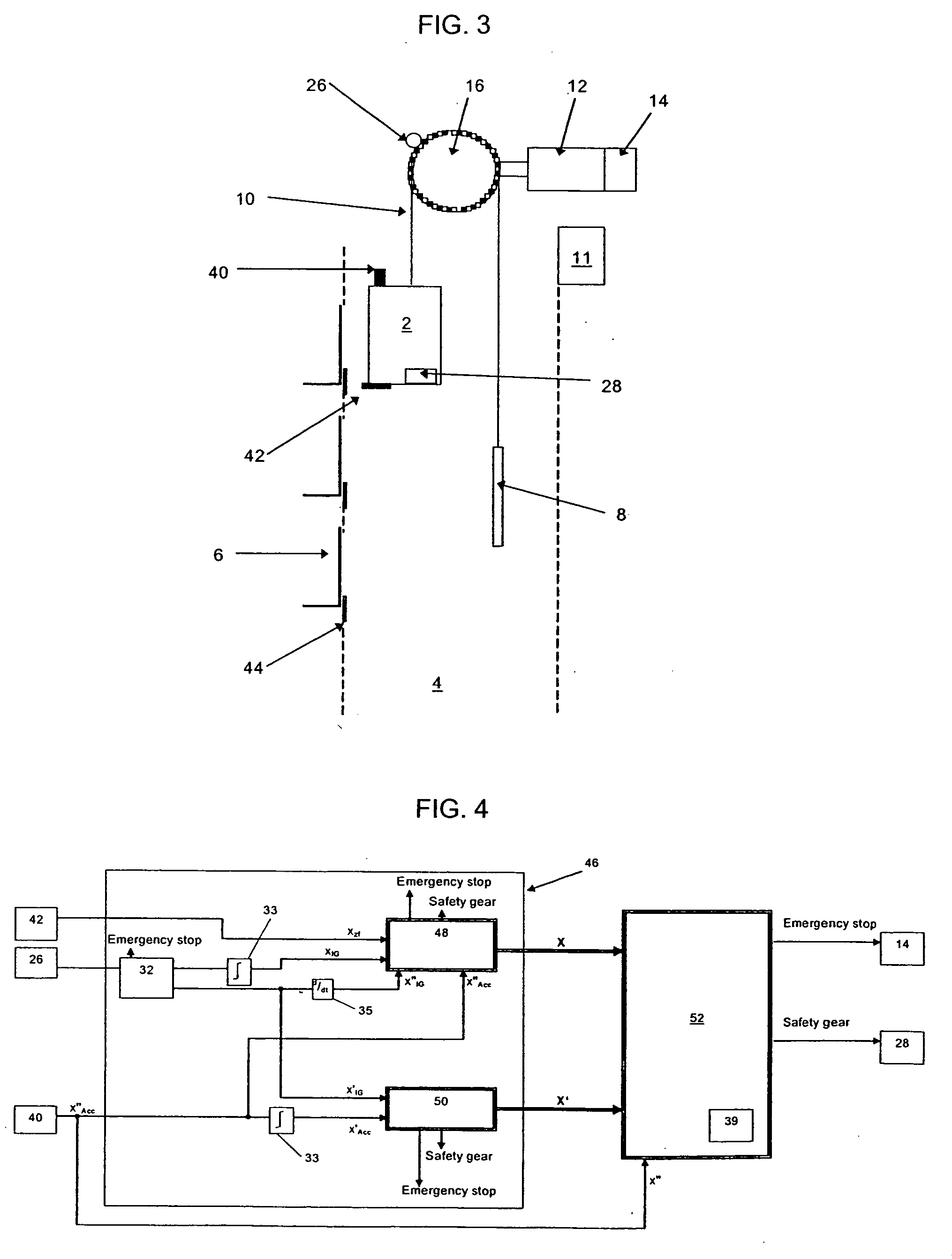
[0037]FIGS. 3 and 4 show the present invention in which the shaft magnets 24 and magnetic detector 22 of the previous embodiment have been replaced with conventional zonal flags 44 symmetrically arranged 120 mm above and below each landing floor level together with an optical reader 42 mounted on the car 2 to detect the flags 44. Additionally, the absolute position encoder 18 has been replaced by an accelerometer 40 mounted on the car 4.

[0038] Within the data verification unit 46 of the present embodiment, the signal XIG derived from the incremental pulse generator 26 is compared with and calibrated against the position signal XZF from the optical reader 42. The distance ΔXZF between successive flags 44 is recorded and compared to the corresponding distance ΔXIG derived from the incremental pulse generator 26. If this comparison gives rise to a deviation in the two distances of two percent or more then an emergency stop is initiated by de-energizing the motor 12 and actuating the br...


PUM


Abstract

A method and system for supervising the safety of an elevator having a car driven by a drive within a hoistway wherein a travel parameter (XABS,X″Acc,X′IGB) of the car is sensed and continually compared with a similarly sensed travel parameter (X′IG) of the drive. If the comparison shows a large deviation between the two parameters, an emergency stop is initiated. Otherwise one of the travel parameters (XABS,X″Acc X′IGB; X′IG) is output as a verified signal (X;X′). The verified signal is then compared with predetermined permitted values. If it lies outside the permitted range then an emergency stop is initiated.

Description

BACKGROUND OF THE INVENTION [0001] The present invention relates to an elevator supervision method and system which greatly simplify the components used in and the architecture of the safety chain but yet enhance the operating performance of an elevator. [0002] Historically it has been standard practice within the elevator industry to strictly separate the collection of information for safety purposes from that for elevator control purposes. This is partly due to the fact that the elevator controller requires information at high precision and frequency regarding the car's position and speed, whereas the most important factor for the safety chain is that the information supplied to it is guaranteed as fail-safe. Accordingly, while the sensor technology used to supply the controller with information has improved dramatically over recent years, the sensors used in elevator safety chains are still based on relatively old “tried and trusted” mechanical or electromechanical principles wit...

Claims


Application Information

Patent Timeline
IPC IPC(8): B66B1/28B66B5/06B66B5/02
CPCB66B5/0031B66B5/02
Inventor ANGST, PHILIPP
Owner INVENTIO AG
Why Eureka
Try Eureka