
Method and apparatus for detecting high-energy radiation using a pulse mode ion chamber

a pulse mode and ion chamber technology, applied in the field of high-energy radiation monitoring and detection, can solve the problems of compromising the accuracy of measurements, difficult to accurately determine neutron flux, and even worse situation

Active Publication Date: 2005-12-08
THERMO FISHER SCIENTIFIC INC
View PDF12 Cites 11 Cited by
  • Summary
  • Abstract
  • Description
  • Claims
  • Application Information

AI Technical Summary

Benefits of technology

"The invention is about a method and system for measuring high-energy radiation flux. The method involves applying a positive voltage to electrodes in an ion chamber filled with a gas capable of forming charged ions by the high-energy radiation, measuring a positive ion current signal related to ion currents induced by the positive voltage, applying a negative voltage to the electrodes, measuring a negative signal related to ion currents induced by the negative voltage and determining a magnitude of the high-energy radiation flux based on the ion current signal. The system includes an ion chamber, two electrodes, and a circuit connected to the two electrodes, which is configured to provide an alternating polarity drive voltage to the two electrodes and to measure an electrical current across the two electrodes. The technical effects of the invention are improved accuracy and reliability in measuring high-energy radiation flux, which is important for various applications such as radiation safety monitoring and environmental monitoring."

Problems solved by technology

However, the ion currents generated in these processes are extremely small (on the order of 10−12 amp), making it very difficult to accurately determine neutron flux.
In addition, temperature and humidity changes in various electronic components, cables, etc. can further compromise the accuracy of the measurements.
The situation is even worse under field conditions, which often include wide variations in temperature and humidity.
Furthermore, instability in leakage currents can also significantly degrade the accuracy of repeat measurements.

Method used


Image

  • Method and apparatus for detecting high-energy radiation using a pulse mode ion chamber
  • Method and apparatus for detecting high-energy radiation using a pulse mode ion chamber
  • Method and apparatus for detecting high-energy radiation using a pulse mode ion chamber

Examples


Embodiment Construction

[0021] Embodiments of the invention relate to ion chambers for measuring high-energy radiations. “High-energy radiation” as used herein refers to neutron, X-ray, gamma ray, α particles, and β particles. For clarity of illustration, the following description uses an ion chamber for neutron detection as an example; however, embodiments of the invention are not so limited. An ion chamber for neutron counting in accordance with embodiments of the invention is operated in a pulse mode, as opposed to the conventional continuous mode.

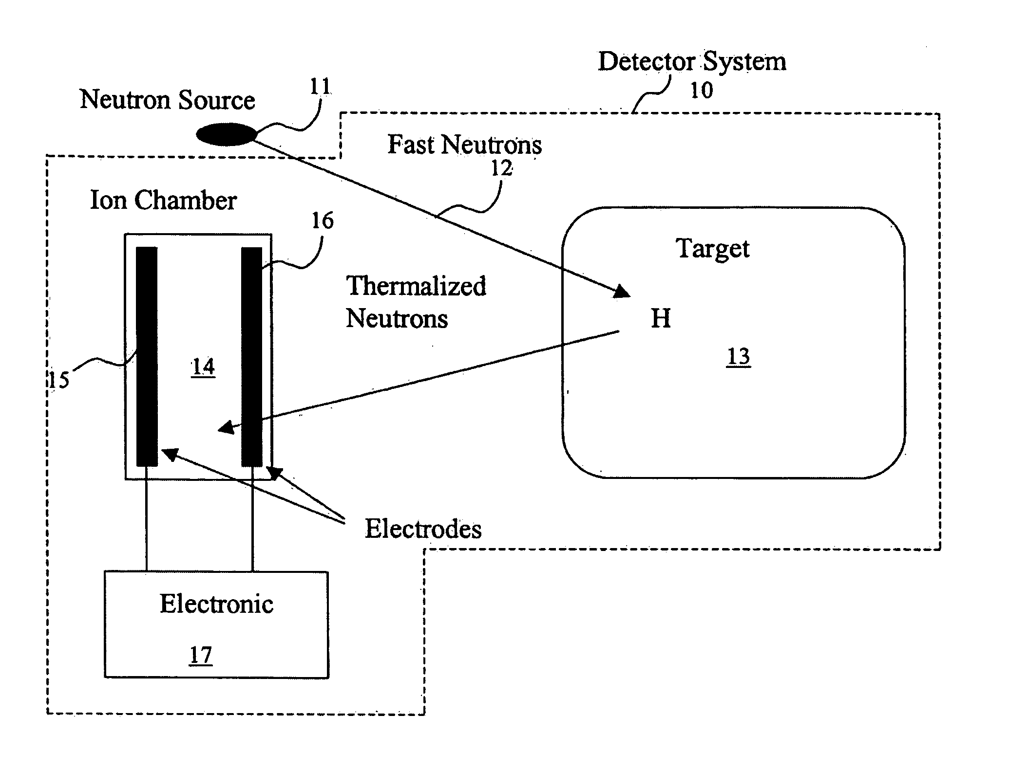
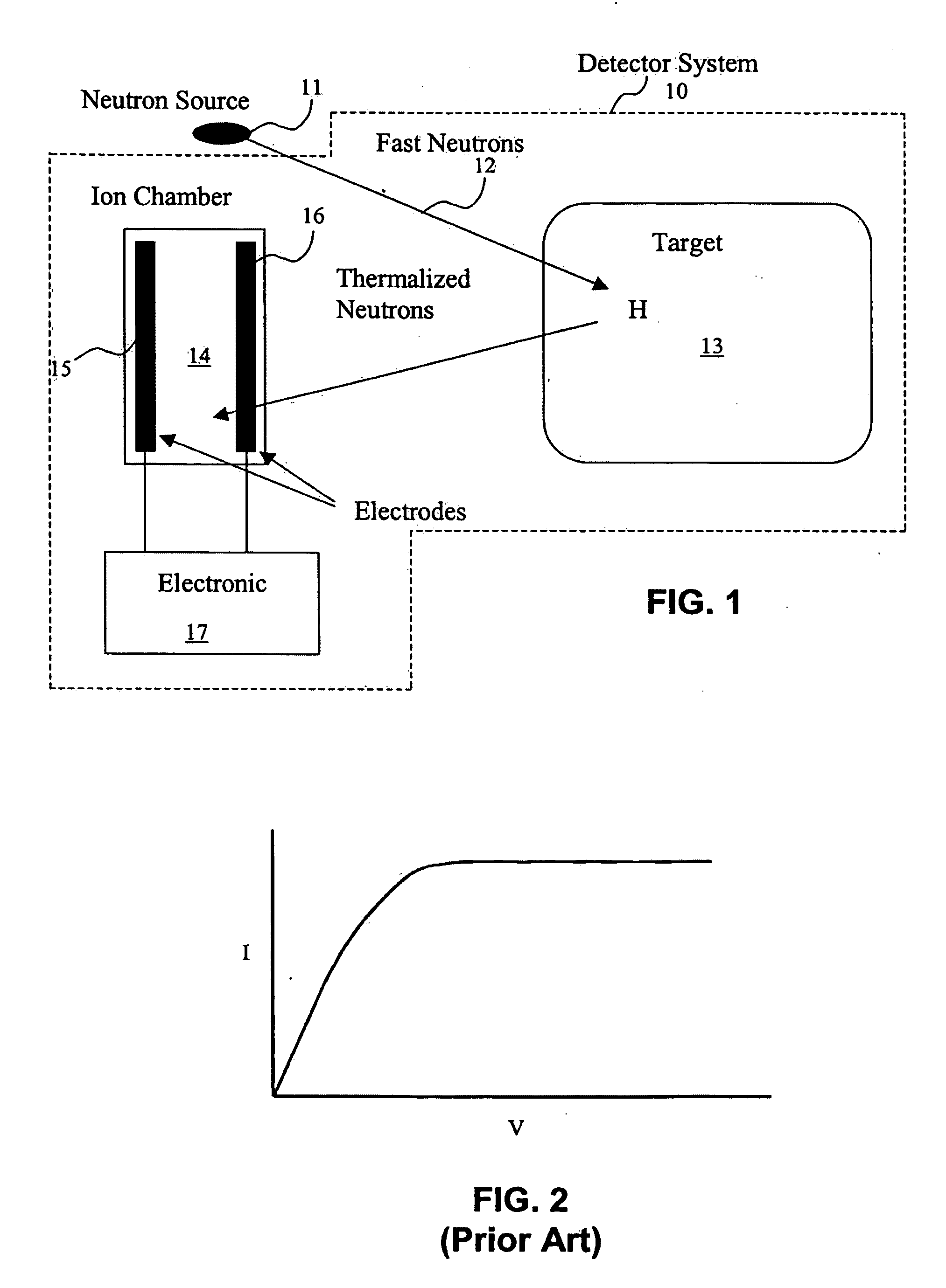
[0022]FIG. 1 shows a conventional detector system 10 for neutron detection. As shown, neutron source 11 generates fast neutrons 12, a fraction of which will scatter into the target chamber 13, which may be filled with a hydrogenous material. “Hydrogenous material” refers to a material having hydrogen nuclei. The neutron source 11 is not part of the detector system 10. The fast neutrons 12 collide with the hydrogen nuclei in the target chamber 13. Hydrogen nuc...


PUM


Abstract

A method for measuring high-energy radiation flux includes applying a positive voltage to electrodes in an ion chamber filled with a gas capable of forming charged ions by a high-energy radiation, measuring a positive ion current signal related to ion currents induced by the positive voltage, applying a negative voltage to the electrodes, measuring a negative signal related to ion currents induced by the negative voltage, and determining a magnitude of the high-energy radiation flux based on the ion current signal.

Description

CROSS-REFERENCE TO RELATED APPLICATIONS [0001] This application is a continuation-in-part of U.S. patent application Ser. No. 10 / 815,157, filed on Mar. 31, 2004. That application is assigned to the assignee of the present invention, and it is incorporated by reference in its entirety.BACKGROUND OF INVENTION [0002] 1. Field of the Invention [0003] The invention relates generally to high-energy radiation monitoring and detection; more particularly, it relates to an ion chamber for detecting high-energy radiation. [0004] 2. Background Art [0005] Detectors of high-energy and ionizing radiations are used in various applications. Such detectors, for example, include ion chambers, proportional counters, Geiger-Mueller counters, and scintillation counters. Among these, ion chambers are commonly used in neutron detectors. FIG. 1 shows a basic system for neutron detection that includes a target chamber 13, an ion chamber 14, and electronics. Fast neutrons 12 are produced by a neutron source 1...

Claims


Application Information

Patent Timeline
Patent Type & Authority Applications(United States)
IPC IPC(8): G01T1/185G01T3/00H01J47/02H01J47/12
CPCG01T3/008G01T1/185
Inventor ESIN, ALEXANDER JOSEPHMASTEROV, MICHAEL
Owner THERMO FISHER SCIENTIFIC INC
Learn More