Vehicle-mounted electrical generator control system enabling suppression of supply voltage spikes that result from disconnecting electrical loads

a technology of electrical generators and control systems, applied in the control of electric generators, electric devices, transportation and packaging, etc., can solve problems such as voltage spikes of significant amplitude, and affecting the operation of electrical generators

Active Publication Date: 2005-12-08
DENSO CORP
View PDF2 Cites 58 Cited by
  • Summary
  • Abstract
  • Description
  • Claims
  • Application Information

AI Technical Summary

Benefits of technology

[0010] It is an objective of the present invention to overcome the above disadvantages of the prior art, by providing a vehicle generator control system whereby (for each of one or more specific electrical loads) occurrence of a voltage spike in the generator output voltage, when a specific electrical load is disconnected from the electrical generator output, is prevented, or the amplitude of such a voltage spike is substantially reduced, by ensuring that at the time point of disconnection of that specific electrical load, the output current of the electrical generator has been reduced by an appropriate amount.

Problems solved by technology

With such a prior art generator control method, a certain amount of delay will occur between the time point at which the electrical load is removed and the point at which control of generator output (reduction of the generated current level) becomes fully effective.
Hence, a voltage spike that is of significant amplitude may occur at the time of load disconnection.
As shown, a voltage spike appears in the battery voltage (i.e., the output voltage of the electrical generator), and such voltage transients can have serious adverse effects upon the operation of various equipment of the vehicle, such as an ECU that performs overall control of the vehicle, equipment that controls the power steering system of the vehicle, etc.
In particular, if the level of current being supplied to the electrical load prior to its disconnection is high, and / or the battery is fully charged, or almost fully charged, then such a voltage spike will be large in amplitude.

Method used


Image

  • Vehicle-mounted electrical generator control system enabling suppression of supply voltage spikes that result from disconnecting electrical loads
  • Vehicle-mounted electrical generator control system enabling suppression of supply voltage spikes that result from disconnecting electrical loads
  • Vehicle-mounted electrical generator control system enabling suppression of supply voltage spikes that result from disconnecting electrical loads

Examples


first embodiment

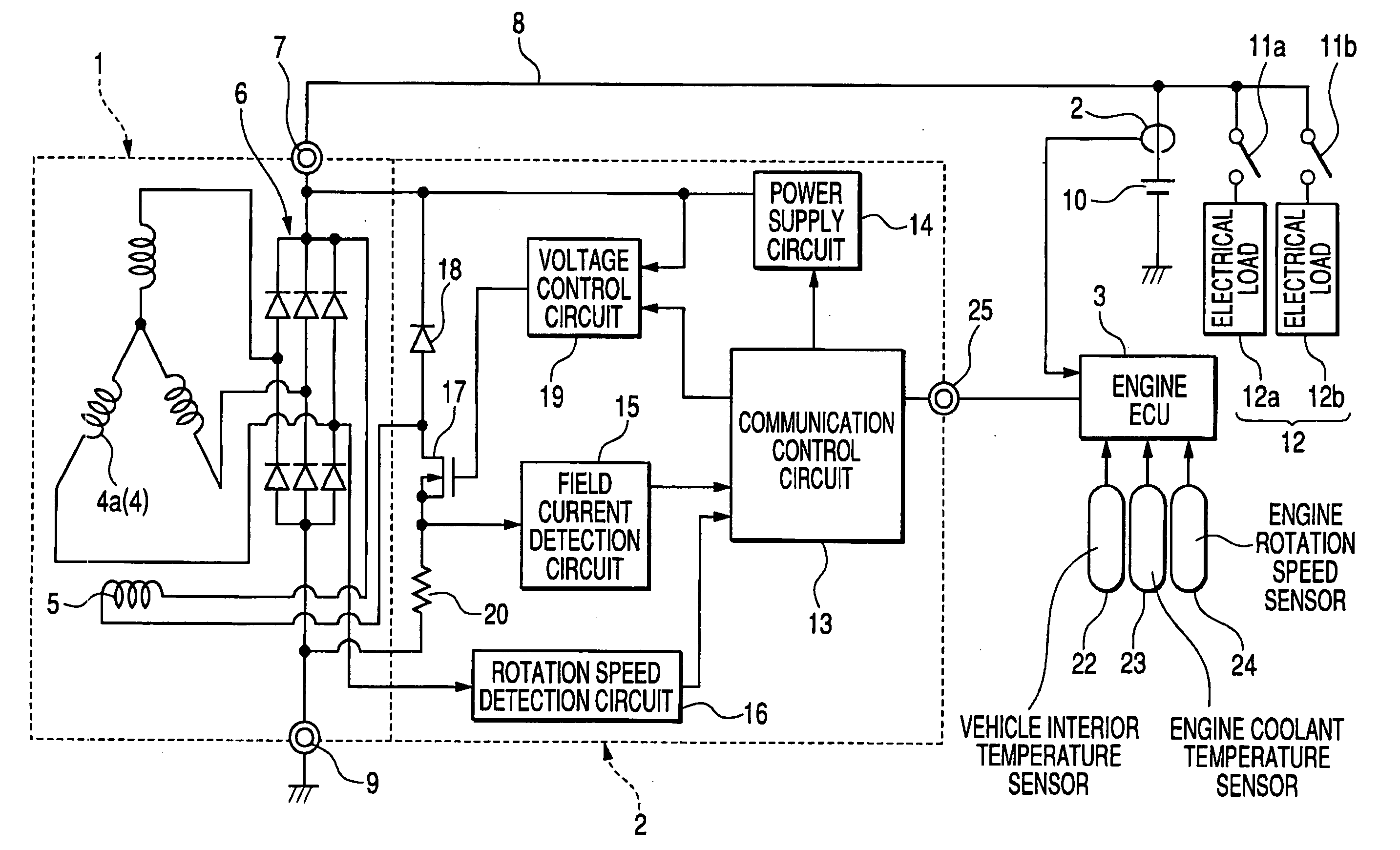
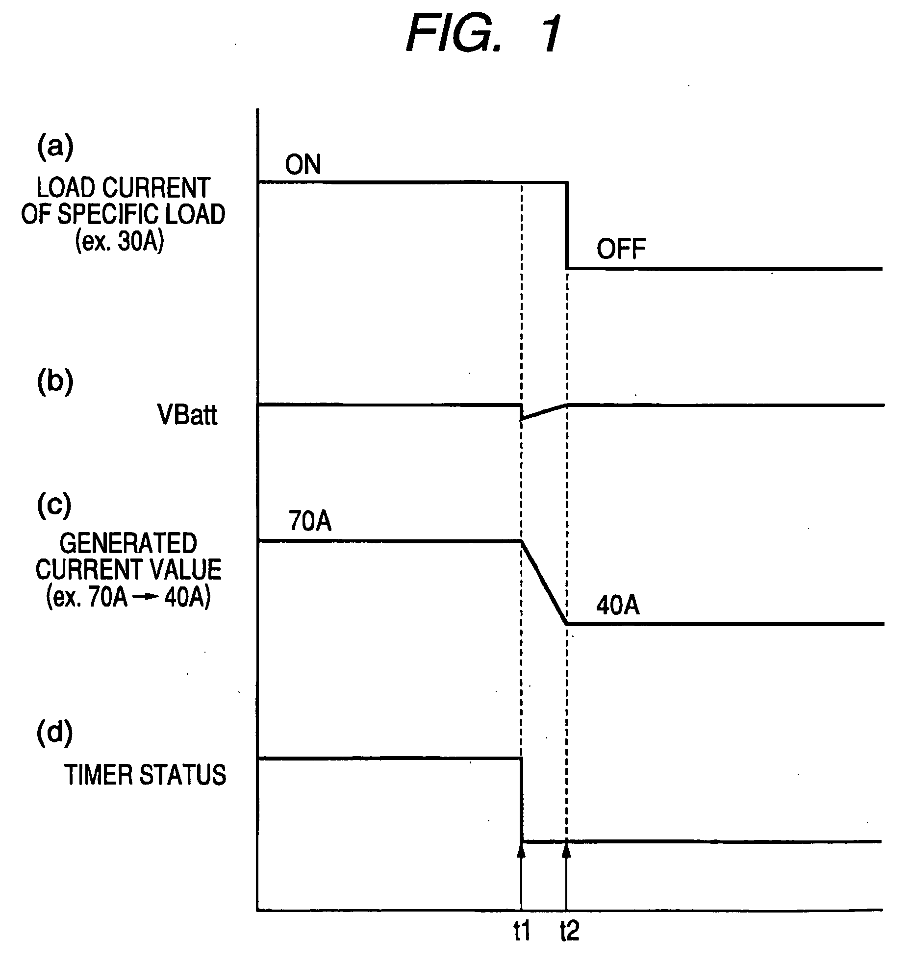
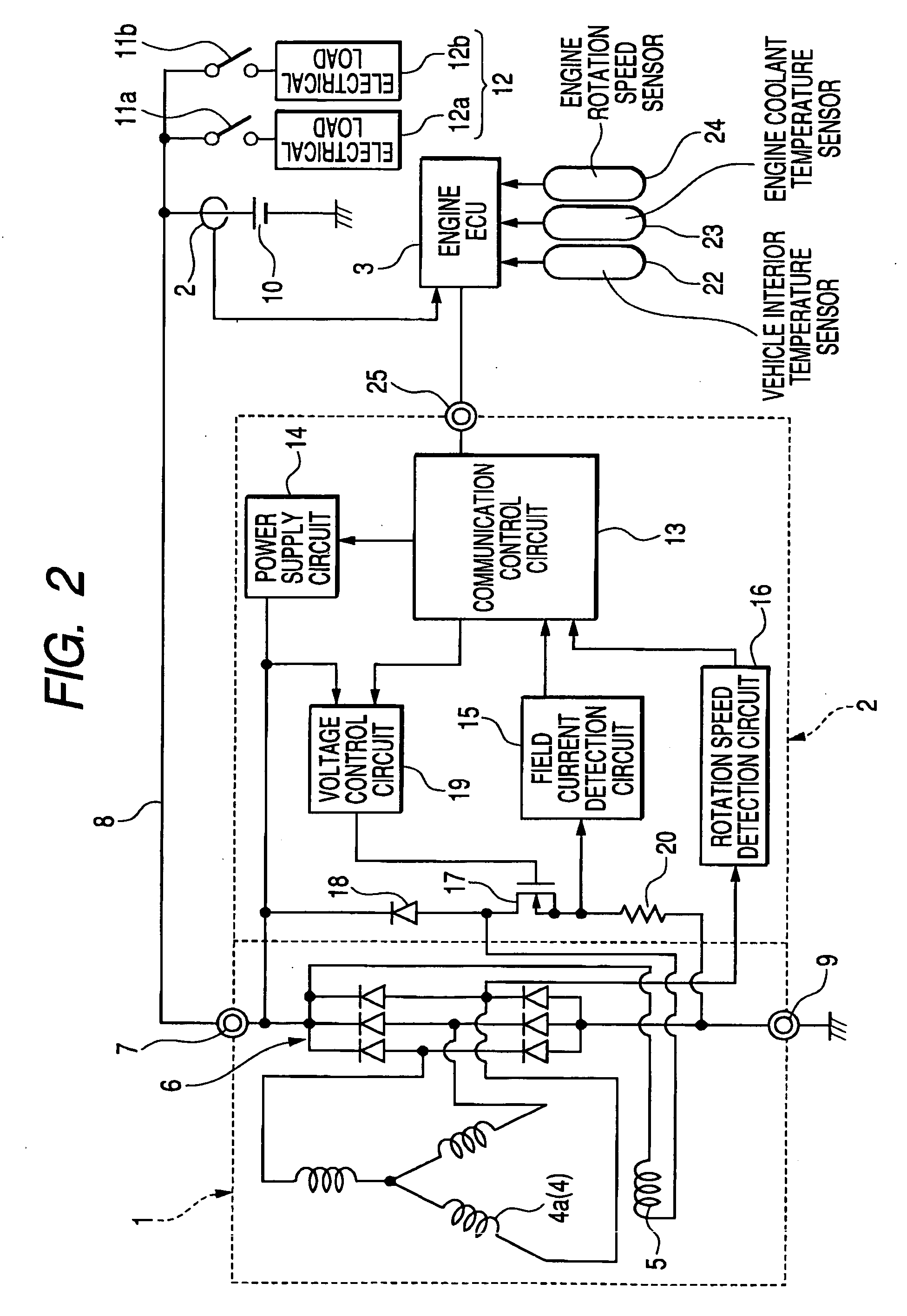
[0033]FIG. 1 is a timing diagram for use in describing the operation of a first embodiment of a vehicle generator control system. FIG. 2 is a general system block diagram of this embodiment, which is constituted as a combination of a regulator 2 and an engine ECU 3. The regulator 2 controls the output voltage of an electrical generator 1 (referred to in the following simply as the generator 1) formed of a 3-phase alternator having Y-configuration phase windings 4 and a field winding 5 that is driven for rotation by the vehicle engine (not shown in the drawings) to produce a rotating magnetic field, and a full-wave rectifier 6 which rectifies the 3-phase output voltages of the phase windings 4, to supply a positive DC output voltage supplied via a B terminal 7 to a power supply lead 8. The negative-voltage side of the rectifier circuit 6 is connected via an E terminal 9 to the vehicle ground potential.

[0034] The AC voltage of a phase winding 4a is detected for use in detecting the s...

second embodiment

[0060] With the first embodiment, during operation in the generated output restraint mode described above, a target value of generated output current from the generator 1 is calculated by subtracting the load current of the specific electrical load 12a from the value of output current that is being generated by the generator 1 at the pre-disconnection time point. That is to say, it is assumed not only that the same respective levels of load current will continue to be supplied to each of the electrical loads other than the load 12a, after the disconnection of load 12a, but also that substantially the same level of charge current is to be drawn by the battery 10. However it is possible that for example prior to disconnection of the specific electrical load, the battery 10 is at a low state of charge, but that the maximum level of output of the generator 1 at that time is insufficient to supply all of the electrical loads while also supplying a sufficient level of charging current to ...

third embodiment

[0067] In the prior art, when the battery 10 is fully charged or is close to the fully charged condition, then disconnection of an electrical load from the generating output voltage will result in a substantial voltage spike as described above referring to FIG. 4. This is due to the fact that when the battery 10 is close to being fully charged, with the output voltage of the generator 1 being higher than the internal voltage of the battery 10, any increase in the output voltage of the generator 1 will not result in a significant increase in charging current that is drawn by the battery 10. However if the battery 10 is in a low state of charge, then an increase in the output voltage of the generator 1 will cause a significant increase in the level of charging current. Hence, if an electrical load is disconnected from the output voltage of the generator 1 when the battery 10 is in a low state of charge, although the level of that output voltage will tend to immediately increase, this ...


PUM


Abstract

A vehicle generator control system detects a time point at which an electrical load is to be disconnected from the generator output, with the detection being achieved prior to that disconnection time point, and initiates a lowering of the generated current of the generator by an amount equal to the load current of that electrical load. The generated current of the generator is thereby reduced, by the time of the disconnection, to a value whereby substantially no voltage spike is produced in the generator output voltage.

Description

[0001] This application is based on and incorporates herein by reference Japanese Patent Application No. 2004-169702 filed on Jun. 8, 2004. BACKGROUND OF THE INVENTION [0002] 1. Field of Application [0003] The present invention relates to a control system of an electrical generator of a vehicle, and in particular to an electrical generator control system whereby the production of voltage spikes in a supply voltage, resulting from disconnection of an electrical load, can be substantially suppressed. [0004] 2. Description of Prior Art [0005] A motor vehicle is equipped with an electrical generator which is in general constituted as an alternator (e.g., 3-phase AC generator) that is driven by the vehicle engine, in combination with a rectifier circuit, to produce an unsmoothed DC output voltage. The electrical generator serves not only for charging the storage battery of the vehicle (referred to in the following simply as the battery) but also for supplying power to various types of el...

Claims


Application Information

Patent Timeline
Patent Type & Authority Applications(United States)
IPC IPC(8): H02H3/02H02P9/30H02H7/06H02H7/18H02J1/14H02J7/14
CPCH02H3/021H02H7/067H02P9/102H02J7/1438H02J1/14
Inventor KONISHI, TOSHIYA
Owner DENSO CORP
Why Eureka
Try Eureka