
Ink jet recording method and ink jet recording apparatus

a recording method and ink jet technology, applied in the direction of railway signalling, transportation and packaging, nuclear engineering, etc., can solve the problems of inability to meet this requirement, inability to meet the requirements of direct ejection system, and the choice of recording medium is subject to strict constraints on the choice of recording medium, so as to reduce the fluidity of ink, suppress beading and/or bleeding, and reduce the moisture of ink image

Inactive Publication Date: 2005-12-08
CANON KK
View PDF14 Cites 82 Cited by
  • Summary
  • Abstract
  • Description
  • Claims
  • Application Information

AI Technical Summary

Benefits of technology

[0017] An object of the present invention is to provide an ink jet recording method and an ink jet recording apparatus permitting image formation with a high degree of color reproducibility while alleviating the influences of the ink-absorbency of the recording medium and the color of the undercoat.
[0018] According to a first aspect of the present invention, there is provided an ink jet recording method comprising: a first applying step of applying ink to an intermediate transfer body with a first recording head according to image data, a transferring step of transferring the ink applied to said intermediate transfer body to a recording medium, a treating step of carrying out, ahead of said transferring step, treatment to reduce the fluidity of the ink to be applied to said intermediate transfer body, and a second applying step of applying, ahead of said transferring step, a white material to at least part of a first area to which said ink is to be applied on said intermediate transfer body or to at least part of a second area to which said ink is to be transferred on said recording medium.
[0023] In a mode of implementing the present invention, an image is formed by applying ink with a recording head to an intermediate transfer body by using a method of reducing the fluidity of the ink (for instance by accelerating the drying of the ink image formed on the intermediate transfer body, reducing the moisture of the ink image on the intermediate transfer body, or applying a reaction liquid which coagulates color materials in ink). This enables an ink image suppressed in beading and / or bleeding to be formed on the intermediate transfer body. Further, ahead of the transferring step, a white material (e.g. white ink) is applied to at least a first area in which ink dots are formed on the intermediate transfer body or to at least a second area to which the ink dots are transferred on the recording medium. This makes possible reducing the influences the color, pattern and other factors of the recording medium or to highlight the image formed on the recording medium. As a result, an image excelling in color reproducibility can be obtained.

Problems solved by technology

However, the direct ejection system, which constitutes the main stream today, cannot satisfy this requirement.
Thus, ink jet recording by the direct discharge system is subject to strict constraints on the choice of the recording medium.
One of its specific constraints is the effect of the ink-absorbency of the recording medium.
Therefore, differences in ink-absorbency and permeability of the recording medium affect the reproducibility of the image.
Therefore image formation is extremely difficult.
Even an ink-permeable recording medium, if its liquid-absorbency (ink-absorbency) is low, would be subject to not only beading and / or bleeding but also a phenomenon known as feathering, in which ink permeates along fibers within the recording medium and accordingly oozes along the fibers, resulting in a poor image.
Increasing the ink-absorbency of the recording medium would alleviate these problems, but this could invite penetration of ink (to the rear face of the recording medium).
Moreover, recycled paper is in expanding use today, a circumstance that contributes to further increasing hue differences among recording media.
However, the system disclosed by this Japanese Patent Application Laid-Open No. 2001-253065 uses no intermediate transfer body but directly applies color inks for image formation to a recording medium.
Therefore it is unsuitable for recording media which are poor in ink absorbency as discussed above.
However, the technique according to Japanese Patent Application Laid-Open No. 2003-25554, as no white ink is applied to the portion where no visible image is formed, involves a problem that the influences of the color and pattern of the recording medium in the undercoat portion for the visible image cannot be sufficiently alleviated.
As a consequence, the advantages of the ink jet recording system including printing ease and adaptability to small number of copies printing are not yet fully utilized in industrial applications.

Method used


Image

  • Ink jet recording method and ink jet recording apparatus
  • Ink jet recording method and ink jet recording apparatus
  • Ink jet recording method and ink jet recording apparatus

Examples


first embodiment

[0033] In this embodiment, white ink used to alleviate the color and pattern of the recording medium or to highlight the image formed on recording medium is applied to a transfer drum, which functions as an intermediate transfer body, between a step of applying a reaction liquid on to the transfer drum and a transfer step.

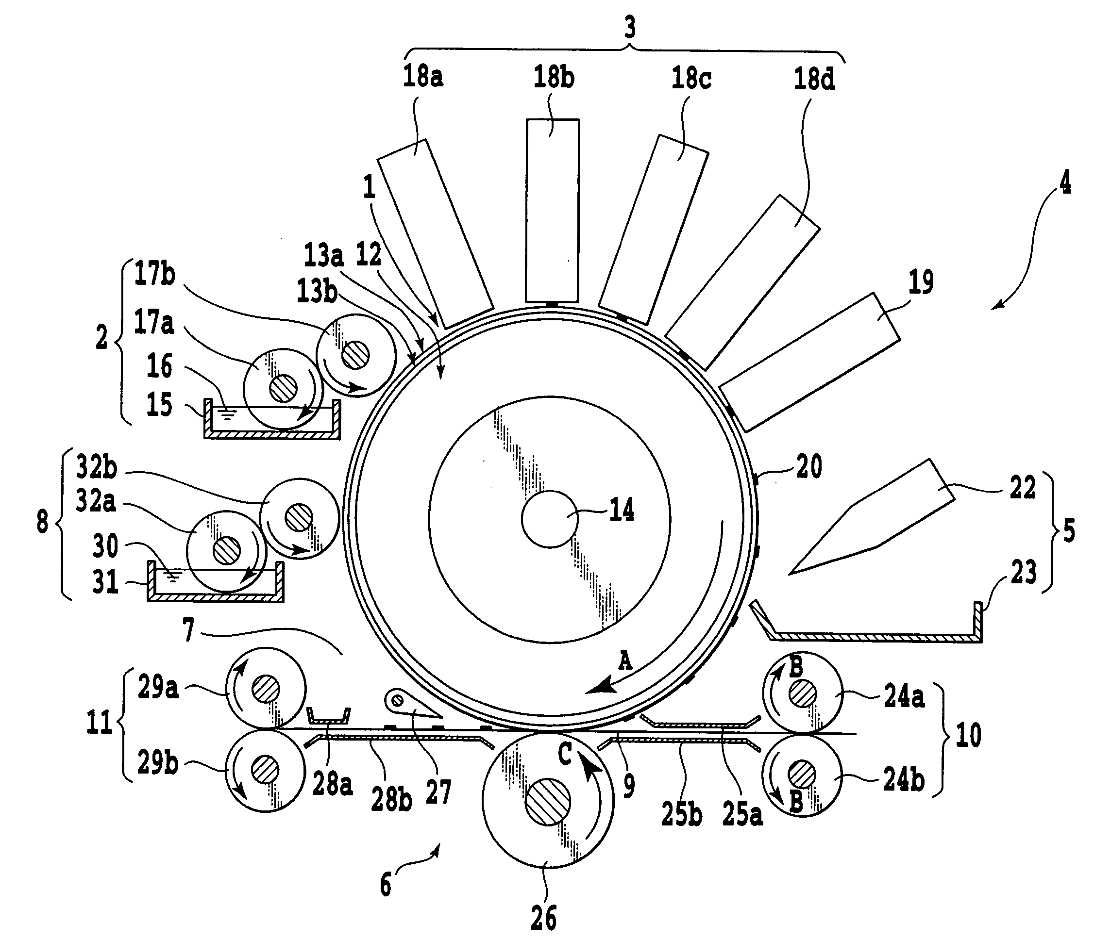
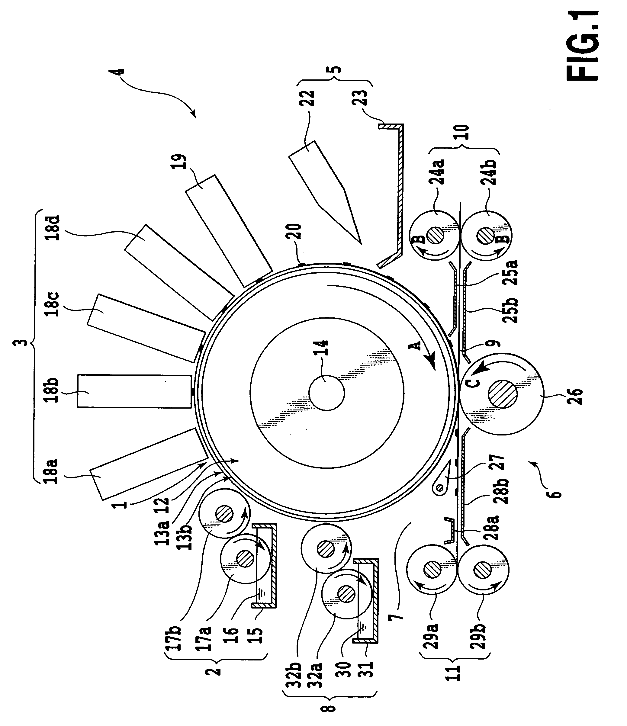
[0034]FIG. 1 is a schematic diagram illustrating the configuration of the image formation unit of an ink jet recording apparatus, which embodies the invention in this mode.

[0035] Referring to FIG. 1, a transfer drum 1 is an intermediate transfer body having a releasable surface layer. This transfer drum 1 is supported on a shaft (not shown) and can be driven by a drum drive unit (not shown) to turn in the direction of arrow A. Along the circumference of the transfer drum 1, there are arranged from the upstream to the downstream side in the following order a reaction liquid application unit 2 as reaction liquid applying means to apply a reaction liquid for coagula...

example 1

[0158] In this example, an image was formed by using the ink jet recording apparatus embodying the invention in this mode, shown in FIG. 1. In this image formation attempt, reaction liquid R1 and pigment inks K1, C1, M1, and Y1 prepared as described above were used. First, after the transfer drum 1 was coated with reaction liquid R1 to a thickness of above 2 μm, pigment ink Y1, M1, C1, and K1 were sequentially applied with the recording heads 18 to form a coagulated ink image 20 on the transfer drum 1.

[0159] In this sequence, each pigment ink on the transfer drum 1 was reacting with reaction liquid R1, and an image formed on the transfer drum 1 was found satisfactory, free from beading. Every time the ink of another color was superposed, coagulation immediately took place with no undesired phenomenon of beading or bleeding, and the image formed on the transfer drum 1 was confirmed to have high picture quality.

[0160] Next, white ink W1 was ejected from the white ink applying record...

example 2

[0162] In this example, image formation was attempted on a transparent base by using the ink jet recording apparatus embodying the invention as illustrated in FIG. 3.

[0163] Immediately after the transfer drum 1 was coated with the earlier prepared reaction liquid R1 by the reaction liquid application unit 2, white ink W2 was ejected onto the intermediate transfer body by the white ink applying recording head 19. After that, the recording heads 18 applied pigment inks K1, C1, M1 and Y1 to the transfer drum 1 to form an image on the transfer drum 1. As a result, like in Example 1, a coagulated ink image of high picture quality was formed on the transfer drum 1. That coagulated ink image was transferred to the transparent base, which was the recording medium in this case. The result was satisfactory, with the final printed sheet after the transfer again proving excellent in picture quality.

[0164] This example would prove useful where the image is to be viewed from the side reverse to...


PUM

PropertyMeasurementUnit
angleaaaaaaaaaa
critical surface tensionaaaaaaaaaa
surface temperatureaaaaaaaaaa

Abstract

An ink jet recording method and an ink jet recording apparatus permitting image formation with a high degree of color reproducibility while alleviating the influences of the ink-absorbency of the recording medium and the base color is to be provided. A transfer drum is applied a reaction liquid, and inks of different colors are applied by recording heads to the area applied the reaction liquid to form a coagulated ink image on the transfer drum. Ahead of the step to transfer this coagulated ink image to the recording medium, white ink is applied to at least the area of the transfer drum to which ink dots are to be applied or at least the area to which ink dots are to be applied out of the area of the recording medium to which the coagulated ink image is to be transferred.

Description

BACKGROUND OF THE INVENTION [0001] 1. Field of the Invention [0002] The present invention relates to an ink jet recording method and an ink jet recording apparatus, and more particularly to an ink jet recording method and an ink jet recording apparatus by which an ink image is formed on an intermediate transfer body having an ink-repellent surface layer and that ink image is transferred to a recording medium to achieve recording. [0003] 2. Description of the Related Art [0004] Recording systems for image recording apparatuses in current use for recording and outputting computer-drawn images, copied images from printed matters, facsimile images and the like as required by the user include ink jet, electron-photographic, thermal head and dot impact systems. [0005] Of these systems, the ink jet recording system, by virtue of its relatively simple hardware configuration, has many advantages including a low running cost, the ease of reducing the hardware size and color recording / printing...

Claims


Application Information

Patent Timeline
Patent Type & Authority Applications(United States)
IPC IPC(8): B41J2/005B41J2/01B41J2/21B41M5/00
CPCB41J2/0057B41J2/2117B41J2/2114B41M5/0256
Inventor MOURI, AKIHIROTANIUCHI, HIROSHI
Owner CANON KK
Learn More