Eye imaging device

a technology for taking images and eye images, applied in the field of eye image taking devices, can solve the problems of inability to extract iris information, increase the number of trials to form plural images, and the illuminators cannot be disposed at places apart from the camera, etc., and achieve the effect of satisfying eye images

Inactive Publication Date: 2005-12-08
PANASONIC CORP
View PDF2 Cites 29 Cited by
  • Summary
  • Abstract
  • Description
  • Claims
  • Application Information

AI Technical Summary

Benefits of technology

[0005] The present invention contemplates to solve those problems and has an object to provide an eye image taking device, which can acquire a satisfactory eye image at a reduced number of trials even in case a person to be authenticated wears eyeglasses, without disposing a plurality of illuminators at places apart from the camera.

Problems solved by technology

In case the person to be authenticated wears eyeglasses, however, the light reflected by the eyeglasses (as will be briefly called the “eyeglass reflection”) may overlap the iris portion, and the iris information may be unable to be extracted.
When those techniques are applied to a mobile terminal device such as a mobile telephone desired to reduce the size and weight, there arises a problem that the illuminators cannot be disposed at places apart from the camera.
Another problem is that the number of trials is increased to form the plural images.

Method used


Image

  • Eye imaging device
  • Eye imaging device
  • Eye imaging device

Examples


embodiment 1

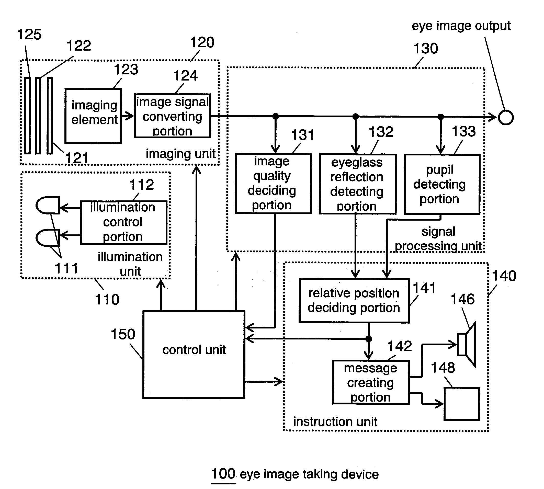
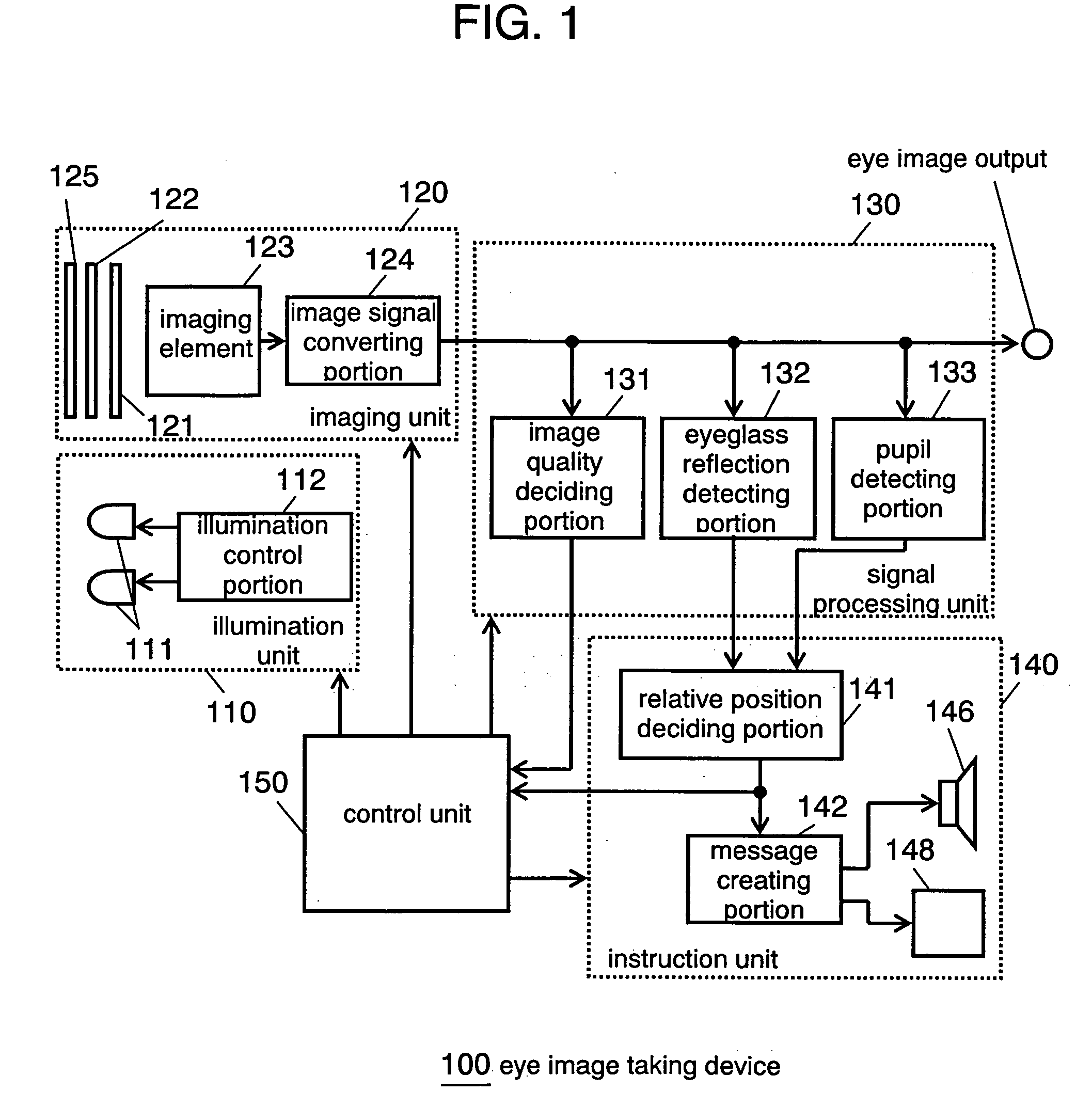
[0017]FIG. 1 is a block diagram showing an eye image taking device according to Embodiment 1 of the invention. Eye image taking device 100 in this embodiment is provided with: illumination unit 110 for irradiating the eye of a person to be authenticated with a near infrared ray; imaging unit 120 for imaging the eye; signal processing unit 130 for detecting the presence / absence of an eyeglass reflection, the position of the reflection and the position of a pupil and for outputting an eye image for authentication to an iris authenticating device or the like; instruction unit 140 for instructing the person to be authenticated; and control unit 150 for controlling the individual blocks.

[0018] Illumination unit 110 includes near infrared ray illuminator 111 and illumination control portion 112, and irradiates the eye of the person to be authenticated with a near infrared ray in a quantity suitable for the eye image acquisition.

[0019] Imaging unit 120 includes lens 121, visible light cu...

embodiment 2

[0034]FIG. 5 is a block diagram of an eye image taking device according to Embodiment 2 of the invention. Like Embodiment 1, the eye image taking device 200 in Embodiment 2 is provided with illumination unit 110, imaging unit 120, signal processing unit 130, instruction unit 240 and control unit 150. What is different from Embodiment 1 is that instruction unit 240 is provided therein with storage portion 243.

[0035] Storage portion 243 is assumed to store the output of relative position deciding portion 141 either in case the eye image incorporation was done in the past to output the speech message or in case the message of the success in the eye image incorporation was outputted. Message creating portion 242 creates not only a proper message on the basis of the output of relative position deciding portion 141 but also a proper message on the basis of the past message stored in storage portion 243.

[0036] Here will be described the operations of the eye image taking device in Embodi...


PUM


Abstract

An eye image taking device comprises: an imaging unit for taking the eye of a person to be authenticated, as an eye image; an illumination unit for illuminating the eye of the person to be authenticated; an eyeglass reflection detecting unit for detecting an eyeglass reflection from the eye image; and an instruction unit for instructing the person to be authenticated the movement of the imaging unit or the direction of the face of the person to be authenticated, in case an eyeglass reflection detecting portion detects the eyeglass reflection.

Description

TECHNICAL FIELD [0001] The present invention relates to an eye image taking device to be used as an iris authentication device, which can be installed in a mobile terminal. BACKGROUND ART [0002] Generally, the iris authentication device identifies a person by illuminating the eye of a person to be authenticated with a near infrared ray, by taking the eye image and the circumference image (as will be briefly called the “eye image”) with a camera, by extracting the iris information from the eye image obtained, and by comparing the iris information with the iris information which has already been registered in the iris information database. In this personal authentication, the satisfactory eye image has to be taken highly precisely for extracting the iris information of the person to be authenticated precisely. In case the person to be authenticated wears eyeglasses, however, the light reflected by the eyeglasses (as will be briefly called the “eyeglass reflection”) may overlap the iri...

Claims


Application Information

Patent Timeline
Patent Type & Authority Applications(United States)
IPC IPC(8): A61B3/10A61B5/117A61B3/14G06K9/00G06T1/00
CPCG06K9/00604G06V40/19
Inventor FUJIMATSU, TAKESHIWAKAMORI, MASAHIRO
Owner PANASONIC CORP
Why Eureka
Try Eureka