Optical object discriminating device

a technology of optical object and discriminating device, which is applied in the direction of optical radiation measurement, instruments, cameras, etc., can solve the problems of mechanical reliability deterioration, mechanical type floor surface discriminating sensor reliability problems, contact portion wear, etc., and achieve high reliability, accurate detection of unevenness of any measuring object, and small size

Inactive Publication Date: 2005-12-08
SHARP KK
View PDF4 Cites 16 Cited by
  • Summary
  • Abstract
  • Description
  • Claims
  • Application Information

AI Technical Summary

Benefits of technology

[0015] Accordingly, an object of the present invention is to provide an optical object discriminating device which is

Problems solved by technology

Generally, such devices as mechanical floor surface discriminating sensors which are so constructed as to have a contact portion, particularly those so constructed that the contact portion has a movable portion movable by contact, have suffered various problems including wear of the contact portion (movable portion) or aged deterioration of mechanical reliability.
As a result, the mechanical type floor surface discriminating sensors are problematic in reliability as compared with optical type floor surface discriminating sensors.
On the other hand, suction-pressure type floor surface discriminating sensors involve changes in the degree of vacuum due not only to the type of the floor surface to be

Method used


Image

  • Optical object discriminating device
  • Optical object discriminating device
  • Optical object discriminating device

Examples


first embodiment

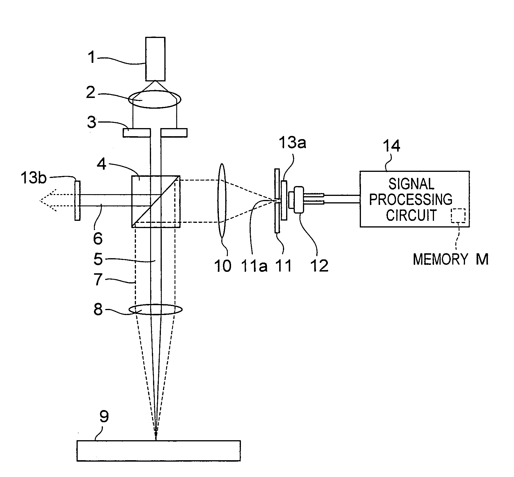
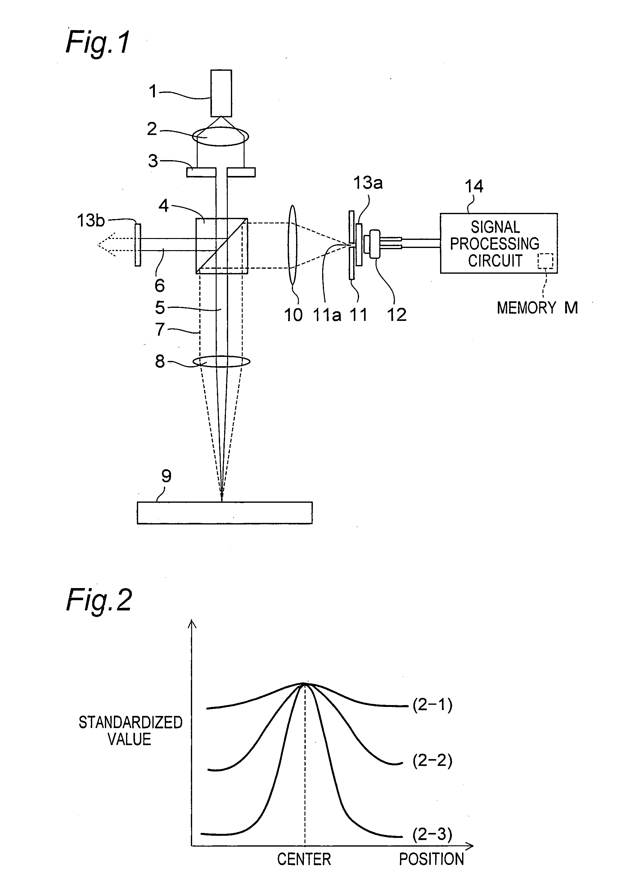
[0480]FIG. 1 is an outlined configurational view of an optical object discriminating device according to a first embodiment of the invention. FIG. 1 shows a locus of a light beam and principal optical parts, and does not show such components as those for holding the optical parts. In this case, the semiconductor light emitting element serving as a light source may be given by an LED (Light Emitting Diode) or LD (Laser Diode) or the like, either of which may be adopted only if its light density on a measuring object 9 is at a desired value or more. It is noted that LDDs are higher in collimatability than LEDs and therefore capable of condensing a light beam into a smaller beam diameter and therefore enhancing the light quantity per unit area. Thus, LDs are preferred. From these reasons, an LD is shown as an example of the semiconductor light emitting element in this embodiment of the invention, and LDs are adopted as an example of the semiconductor light emitting element in the follo...

second embodiment

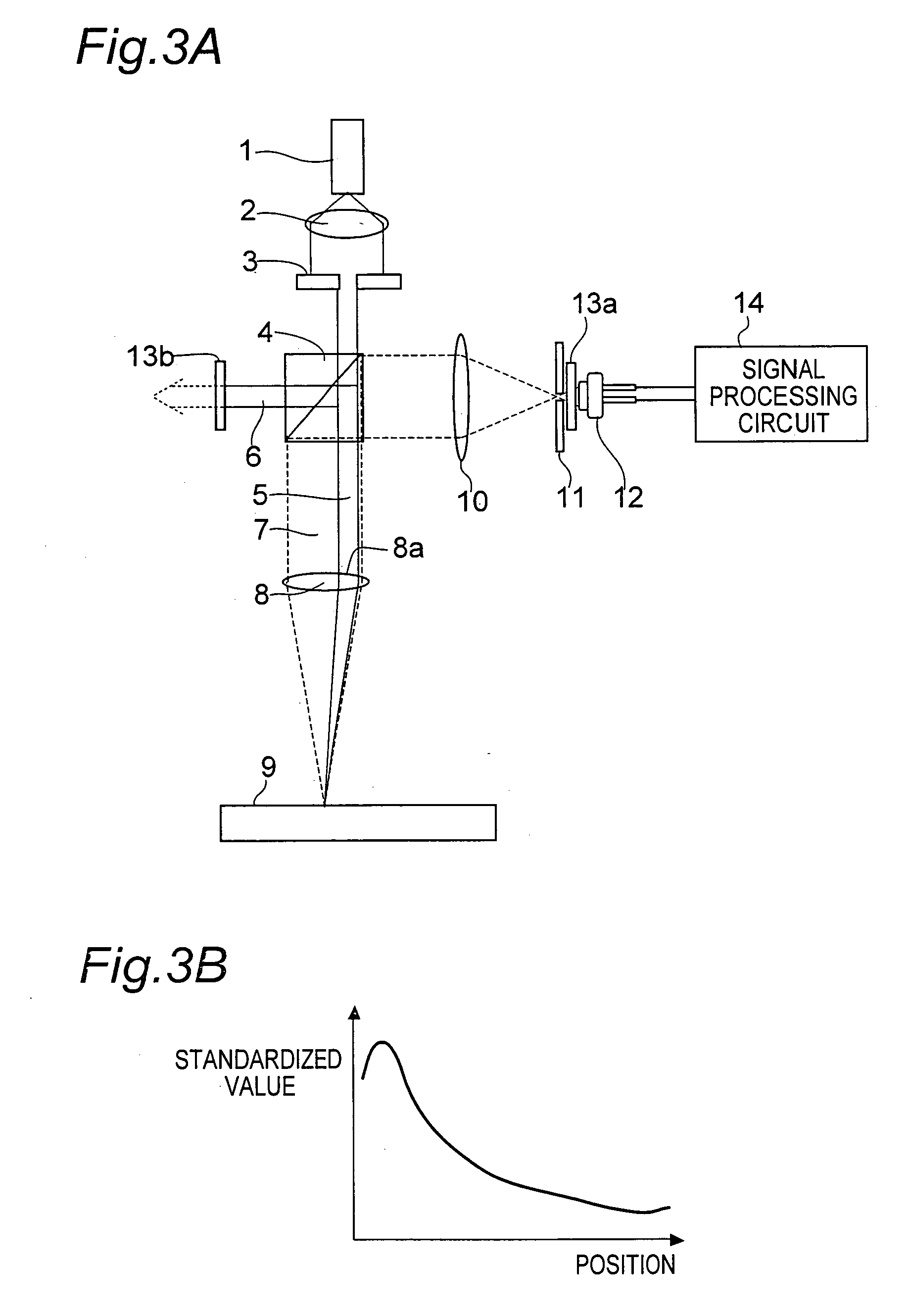
[0510]FIG. 4 shows an outlined configuration of an optical object discriminating device according to a second embodiment of the invention. In FIG. 4, a locus of a light beam and principal optical parts are shown, and such components as those for holding the optical parts are not shown. Also in FIG. 4, the same constituent parts as those of the first embodiment shown in FIG. 1 are designated by the same reference numerals as those of the constituent parts in FIG. 1, and their description is omitted. This second embodiment differs from the foregoing first embodiment in that a mirror 15 as a lead part is included in place of the non-polarization beam splitter 4 of the modification example of the first embodiment.

[0511] In the second embodiment, the first beam 5 outputted from the aperture 3 is incident directly on the edge portion 8a of the objective lens 8, being focused on the measuring object 9 placed at the focal length of the objective lens 8. Further, since the first beam 5 beco...

third embodiment

[0515] Next, FIG. 5 shows an outlined configuration of an optical object discriminating device according to a third embodiment of the invention. In FIG. 5, a locus of a light beam and principal optical parts are shown, and such components as those for holding the optical parts are not shown. Also in FIG. 5, the same constituent parts as those of the first embodiment shown in FIG. 1 are designated by the same reference numerals as those of the constituent parts in FIG. 1, and their description is omitted.

[0516] This third embodiment differs from the foregoing first embodiment in that the linear polarizer 13b is not included while a mirror 15 as an optical axis changing part is included in adjacency to the non-polarization beam splitter 4.

[0517] In this third embodiment, the first beam 5 that has passed through the non-polarization beam splitter 4 is incident on the objective lens 8, while the second beam 6 reflected by the non-polarization beam splitter 4 is reflected by the mirror...


PUM


Abstract

The optical object discriminating device includes a light projecting part which applies light, which is emitted from a semiconductor light emitting element, to a measuring object which is an object to be measured, and a light receiving part which receives reflected light reflected by the measuring object. Between the light receiving part and the measuring object is placed a polarization-state selector part which permits polarized light of a specified polarization direction to pass therethrough. A signal processing part processes a signal outputted by the light receiving part, and measures intensity of light of the polarization direction permitted by the polarization-state selector part to pass therethrough.

Description

[0001] This Nonprovisional application claims priority under 35 U.S.C. §119(a) on Patent Application No. 2004-166694, No. 2004-292588 and No. 2004-361302 filed in Japan on Jun. 4, 2004, Oct. 5, 2004 and Dec. 14, 2004, respectively, the entire contents of which are hereby incorporated by reference. BACKGROUND OF THE INVENTION [0002] The present invention relates to optical object discriminating devices. The invention relates to an optical object discriminating device that discriminates the type of a measuring object, which is an object to be measured, for example, by applying laser beam to the measuring object and measuring a characteristic of depolarization due to reflection of the laser beam. The invention relates to an optical object discriminating device that discriminates, for example, the type of floor surfaces such as carpet, wooden floor and straw tatami mat. [0003] As an example, the invention relates to an optical object discriminating device suited to achieving optimizatio...

Claims


Application Information

Patent Timeline
IPC IPC(8): G03B17/18
CPCG03B17/18
Inventor WADA, HIDEOWATANABE, NOBUHISATAMINAGA, TAKAYUKIKASHIDA, HAJIME
Owner SHARP KK
Why Eureka
Try Eureka