Casing unit for electronic device

a technology for electronic devices and casings, which is applied in the direction of electrical apparatus casings/cabinets/drawers, electrical apparatus construction details, and support structure mounting, etc., can solve the problems of difficult to improve the mounting density of printed circuit boards, difficult to miniaturize printed circuit boards, and difficult to mount electronic components in areas where strain occurs, so as to reduce stress in boards. , the effect of light weight and less strength

Inactive Publication Date: 2005-12-08
DENSO CORP
View PDF6 Cites 26 Cited by
  • Summary
  • Abstract
  • Description
  • Claims
  • Application Information

AI Technical Summary

Benefits of technology

[0028] Like the foregoing, this example mode structure provides the pair of planar-direction positioning members and the vertically positioning member which have the capability of positioning a printed circuit board, as described above. Those positioning members eliminate the necessity for deliberately pressing a printed circuit board and enable the board to be positioned in both the planar and vertical directions, whereby stress in the board can surely be reduced.
[0029] With the casing unit described above, the case and the cover may be made of resin material. In such a case, the electronic device can be manufactured to be light in weight. In the meanwhile, the electronic device has less strength than that of a cover and case made of metal. Because of this, the case and cover are liable to be deformed. Even for the case and the cover made of resin material with such less strength, providing the electronic device with the casing structure set forth above enables the electronic device to have increased rigidity and the assembly is made simpler, which is an excellent feature.
[0030] The casing unit defined above is suitably applied to an engine ECU (electronic control unit) of a vehicle. There is a need for the engine ECU of the vehicle to have lightweight and, in addition, a need arises for increased rigidity to be provided to address issues arising from increased vibrations delivered from the vehicle. For the engine ECU of the vehicle with such needs, the use of the casing structure set forth above enables the provision of an electronic device with increased rigidity and excellent characteristic in assembling capability.

Problems solved by technology

However, with the casing structure formed in a configuration, set forth above, wherein the printed circuit board is pressed to cause the same to be flexed using the resulting reaction force, strain occurs in the printed circuit board, resulting in a difficulty for electronic component parts to be mounted in areas where strain occurs.
Accordingly, it becomes hard to improve mounting density of the printed circuit board with a resultant difficulty in miniaturizing the printed circuit board (physical size of the electronic device).

Method used


Image

  • Casing unit for electronic device
  • Casing unit for electronic device
  • Casing unit for electronic device

Examples


first embodiment

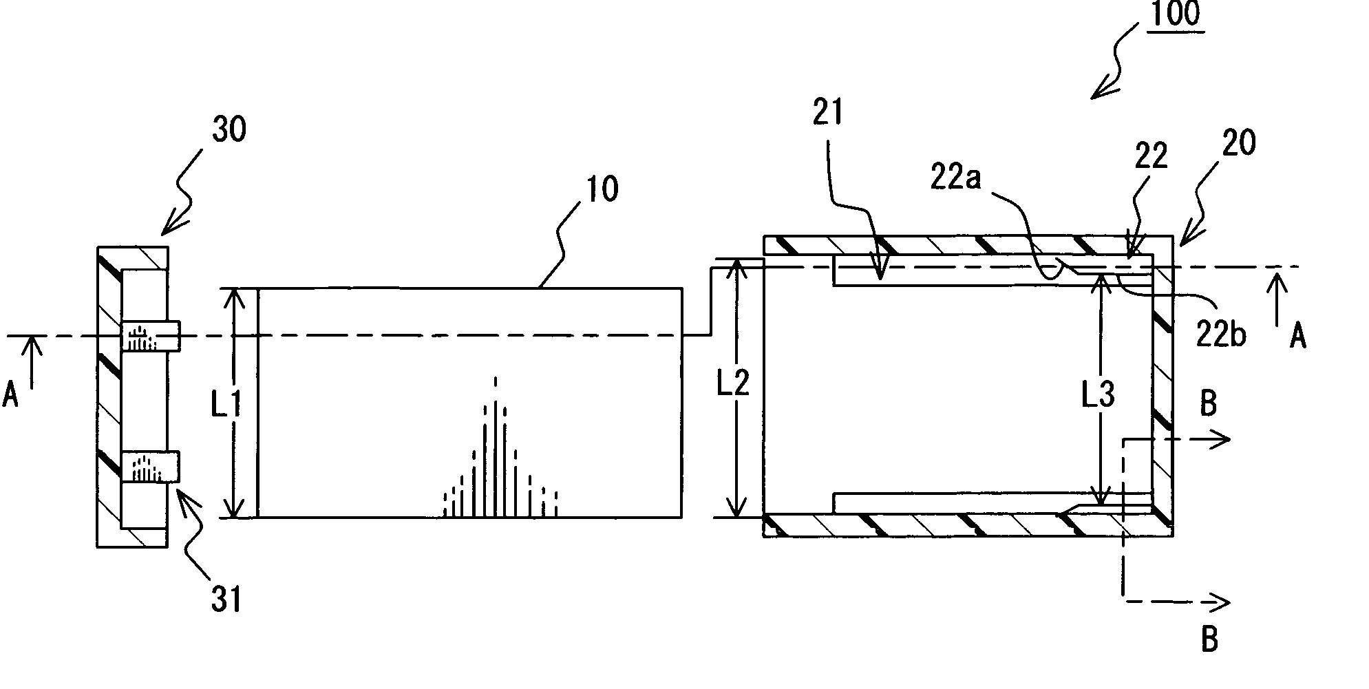
[0046] Referring to FIGS. 1A to 1C-2A to 2C, a casing unit for a casing unit for an electronic device will now be described. The electronic device, shown in conjunction with the present embodiment, is employed as an engine ECU (Electronic Control Unit) of a vehicle.

[0047] As shown in FIGS. 1A to 1C, the electronic device 100 with a casing unit according to the present embodiment is comprised of a printed circuit board 10, on which electronic component parts (not shown) are mounted, a case 20, in which the printed circuit board 10 is accommodated, and a cover 30 by which the case 20 is covered. The present embodiment has a characteristic feature in that the printed circuit board 20 is supported within the casing unit, composed of the case 20 and the cover 30, and the following description will be given with a focus on the case 20 and / or the cover 30.

[0048] The case 20 is formed of resin material (such as propylene) in a box-like configuration with one open end. Both side faces of t...

second embodiment

[0066] A second embodiment according to the present invention will now be described with reference to FIGS. 5A to 5C, in which the upper surface (21a) of the guide 21 is omitted in FIG. 5A.

[0067] The casing structure of the electronic device 100 of the second embodiment is mostly common in structure to the first embodiment and, so, a detailed description of common component parts is omitted with description made with a focus on differing points.

[0068] The second embodiment differs from the first embodiment in that second guide protruding members are provided on the case 20 with a view to positioning and fixing the printed circuit board 10 in a vertical direction thereof.

[0069] The electronic device 100 of the present embodiment includes the first guide protruding members 22 provided on the respective guides 21 of the case 20 as the component elements for permitting the printed circuit board 10 to be positioned and fixed in the planar direction thereof like the first embodiment. A...

third embodiment

[0084] A third embodiment according to the present invention will now be described with reference to FIG. 6 and FIGS. 7A and 7B.

[0085] The casing structure of the electronic device 100 of the third embodiment is mostly common to that of the first embodiment and, so, description of the common component parts are herein omitted while description is made with a focus on differing component parts.

[0086] The third embodiment differs from the first embodiment in that a gap adjuster is provided on the cover 30 to position and fix the printed circuit board 10 in terms of the planar direction thereof.

[0087] In normal practice, the box-like case 20 is formed by injection molding or aluminum die-casting upon flowing component material under melted condition into a die-mold formed in a given configuration. When this takes place, in order to provide an increased stripping capability of the mold for the case 20 to be stripped off and provide improved durability of the mold, it has been a gener...


PUM


Abstract

In a casing unit for accommodating a printed circuit board, a case has a plurality of walls, one of the walls being partially or entirely open to form an open surface through which the board is inserted into the case. Guides, secured on side walls, comprise two guide protruding members each formed to protrude from the side walls and positioned to partly contact both sides of the board to be inserted into the case, whereby the board is positioned in a planar direction thereof. A cover, applied to the case to cover the open surface of the case, comprises a vertically positioning member positioning the board in a vertical direction, when the cover is applied to the case to cover the open surface, by pinching an end of the board in the vertical direction. The end of the board is located in the open surface of the case.

Description

CROSS REFERENCES TO RELATED APPLICATIONS [0001] The present application relates to and incorporates by reference Japanese Patent application Nos. 2004-164851 filed on Jun. 2, 2004 and 2004-287925 filed on Sep. 30, 2004. BACKGROUND OF THE INVENTION [0002] 1. Field of the Invention The present invention relates to a casing unit for electronic devices wherein a printed circuit board, on which electronic component parts are mounted, is supported in an internal space defined by a case and a cover. [0003] 2. Description of the Related Art [0004] In electronic apparatuses, it is frequent that printed circuit boards are arranged in cases for protection, shielding against noise, or other influences. In order to achieve such purposes, there have been various types of cases. Electronic component parts are mounted on a printed circuit board enclosed by a case. One conventional structure for an electronic device, which is categorized into the above case, is disclosed in, for instance, Japanese P...

Claims


Application Information

Patent Timeline
Patent Type & Authority Applications(United States)
IPC IPC(8): H05K5/04H05K7/14H05K5/06H05K5/00
CPCH05K5/0039H05K7/1405
Inventor MORISADA, KAZUTOSHI
Owner DENSO CORP
Why Eureka
Try Eureka