
Modified sinusoidal pulse width modulation for full digital power factor correction

a technology of power factor correction and sinusoidal pulse width, which is applied in the direction of electric variable regulation, process and machine control, instruments, etc., can solve the problems of affecting the dsps, affecting the dsps, and affecting the dsps, and it is difficult to eliminate the third harmonic componen

Inactive Publication Date: 2005-12-08
SEMICON COMPONENTS IND LLC
View PDF17 Cites 48 Cited by
  • Summary
  • Abstract
  • Description
  • Claims
  • Application Information

AI Technical Summary

Benefits of technology

The invention is a converter-controller that includes a feedback circuit, a duty cycle modulator, a counter, and a comparator. The feedback circuit receives a feedback voltage from an output stage and generates a current command signal based on the difference between a reference voltage and the feedback voltage. The duty cycle modulator modifies the duty cycle based on the current command signal and a reference table. The counter produces a periodic signal, and the comparator generates a variable-duty-cycle output current based on the difference between the modified duty cycle and the periodic signal. The technical effect of this invention is to provide a more efficient and accurate control of the converter's output current.

Problems solved by technology

However, price considerations are detrimental to DSPs.
However, an unwanted third harmonic component of about 8˜10% of the input signal typically appears in the output of these converters.
It is difficult to eliminate this third harmonic component by using an EMI filter with a high cut-off frequency, since its frequency is close to the fundamental frequency.

Method used


Image

  • Modified sinusoidal pulse width modulation for full digital power factor correction
  • Modified sinusoidal pulse width modulation for full digital power factor correction
  • Modified sinusoidal pulse width modulation for full digital power factor correction

Examples


Embodiment Construction

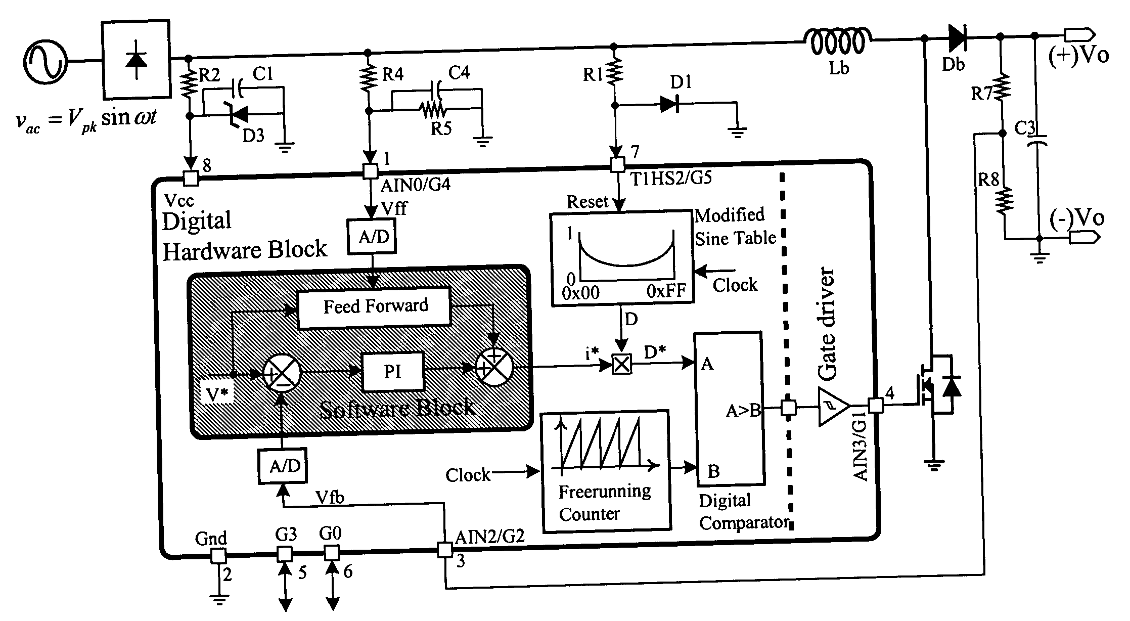
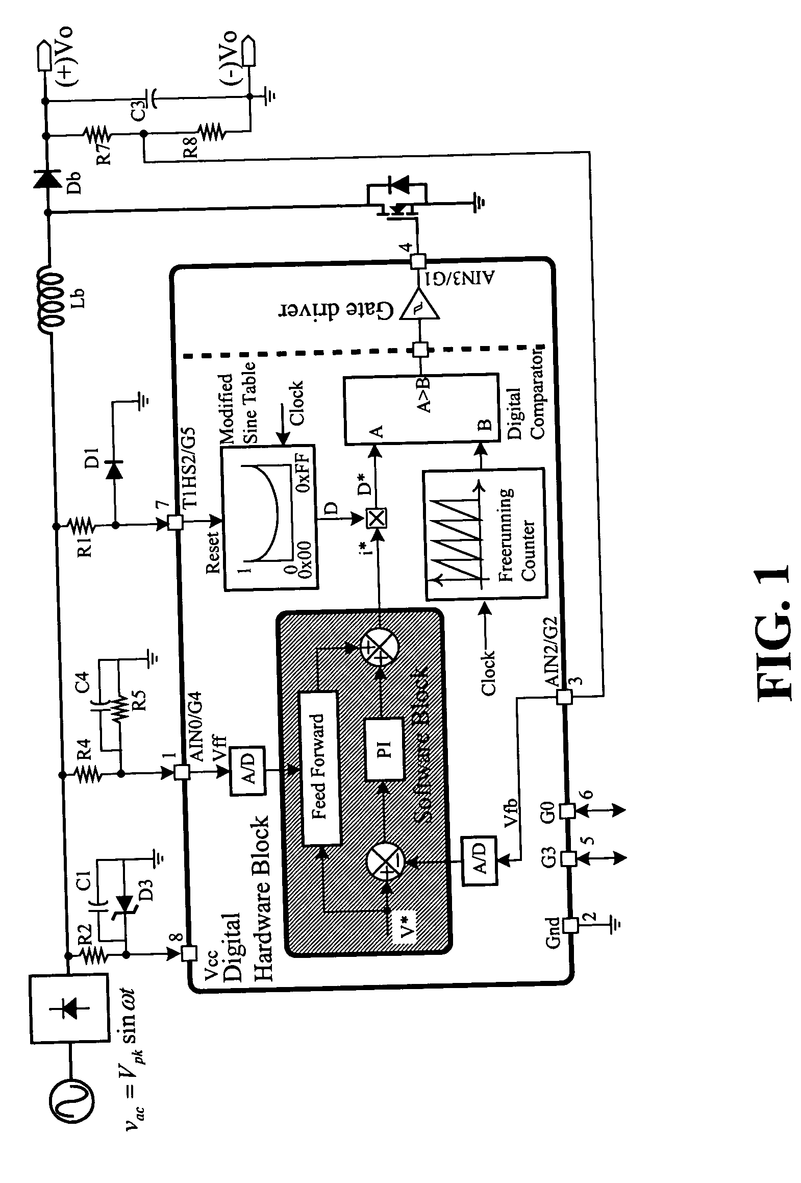
[0016] According to embodiments of the invention a converter-controller with an improved power factor conversion is described in relation to FIGS. 1-9.

[0017]FIG. 1 illustrates an embodiment of converter-controller 100, for controlling the operation of a converter 1. Converter-controller 100 includes a feedback circuit 110, which receives a feedback voltage Vfb from a resistor stepper 124 of output stage 120. Feedback circuit 110 generates a current command signal, which corresponds to the output of digital Proportional-Integral (PI) controller 119. The output of digital PI controller 119 is based on the difference of a reference voltage V* and the feedback voltage Vfb.

[0018] Converter-controller 100 controls the power factor conversion of converter 1 digitally. Accordingly, feedback circuit 110 receives feedback voltage Vfb through a analog-digital converter 113 from output stage 120.

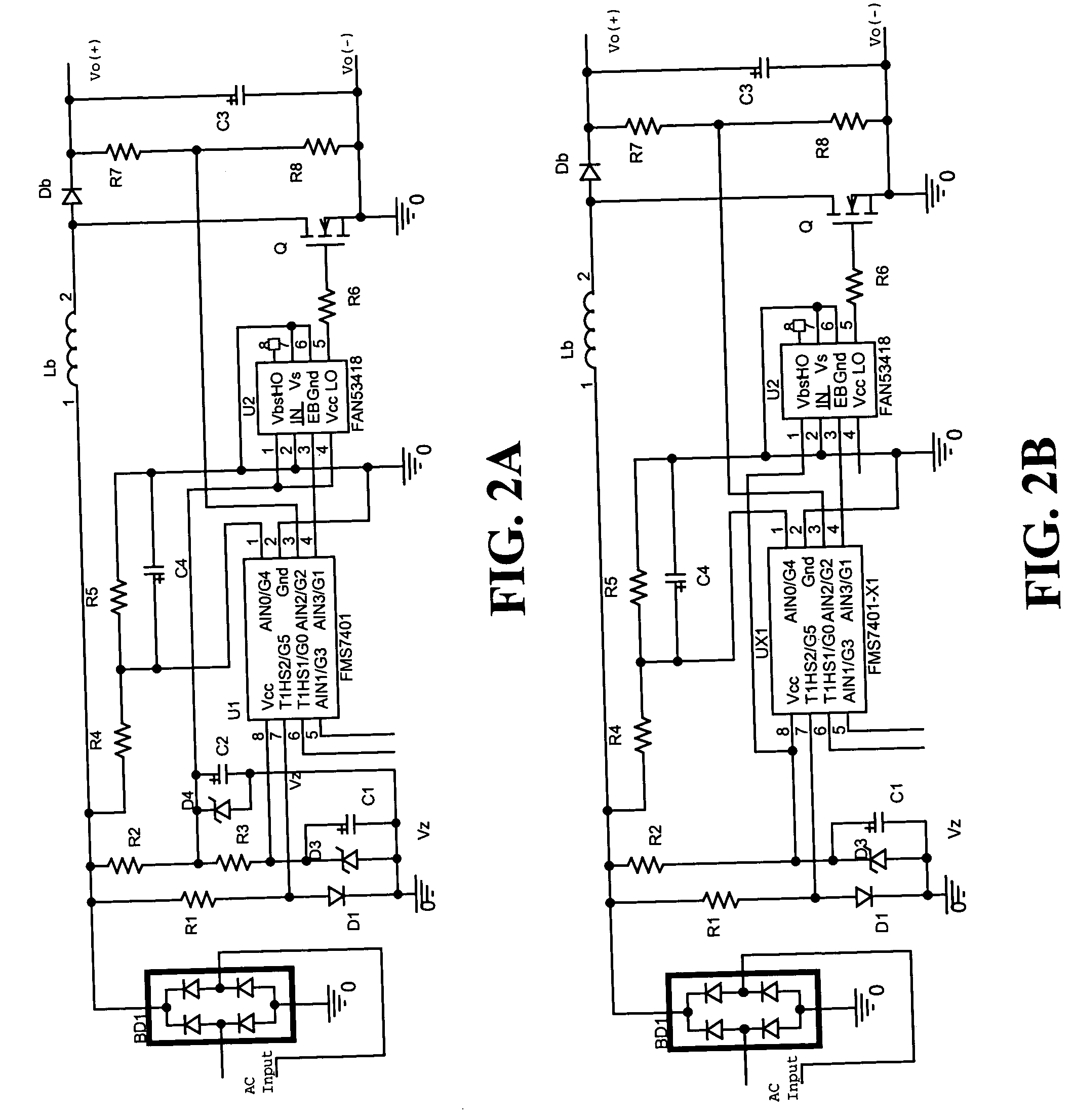
[0019] One embodiment of convert-controller 100 is microcontroller FMS7401 from Fairchild Semicon...


PUM


Abstract

A converter-controller includes a feedback circuit, receiving a feedback voltage from an output stage and generating a current command signal according to the difference of a reference voltage and the feedback voltage. A duty cycle modulator generates a modified duty cycle utilizing the current command signal and a reference table. The controller further includes a counter producing a periodic signal, and a comparator, receiving the modified duty cycle and the periodic signal. The comparator generates a variable-duty-cycle output current corresponding to the difference of the periodic signal and the modified duty cycle.

Description

FIELD OF THE INVENTION [0001] This invention relates in general to converter-controllers, and in particular to digital converter-controllers with an adjustable duty cycle. BACKGROUND OF THE INVENTION [0002] The power factor control method has been utilized in various power supplies. Certain popular methods use an analog controller with a Discontinuous Conduction Mode (DCM) such as the FAN7527B and FAN4812 integrated circuits from Fairchild Semiconductor. Recently there has been a lot of research of possible digital approaches for controlling the power factor of converters. One requirement is that the control speed of the digital controllers should be suitable to deliver a performance comparable to analog controllers. Since Digital Signal Processors (DSPs) have fast calculation speed, they can be used as digital controllers. However, price considerations are detrimental to DSPs. [0003] A simple digital PFC method is to fix the switching frequency and adjust the duty ratio to control ...

Claims


Application Information

Patent Timeline
Patent Type & Authority Applications(United States)
IPC IPC(8): H02M1/00H02M1/42
CPCH02M1/4225H02M3/157Y02B70/126Y02B70/10H03F1/00H03K7/08
Inventor OH, IN-HWAN
Owner SEMICON COMPONENTS IND LLC
Learn More