Full wave seismic recording system

a full wave seismic and recording system technology, applied in seismology, seismology, instruments, etc., can solve the problems of inability to record s-waves, inability to provide sufficient sampling for gaining a true three-dimensional (3d) image, and high cos

Inactive Publication Date: 2005-12-08
ENTRE HLDG
View PDF22 Cites 41 Cited by
  • Summary
  • Abstract
  • Description
  • Claims
  • Application Information

AI Technical Summary

Benefits of technology

[0008] An individual seafloor recorder instrument is also described. In one embodiment, the recorder instrument includes a housing having various seismic sensors disposed therein. The instrument further includes transponders spaced from one another along the housing to enable acoustic communication between the instrument and an acoustic array displaced from the seafloor. A frame assembly may also be provided for facilitating deployment of the instrument and proper positioning of the instrument on the seafloor.

Problems solved by technology

However, towed streamers are generally submerged a short distance from the sea surface, and therefore, are unable to record S-waves, which are unable to travel through seawater.
Also, towed streamers are very vulnerable to damage, expensive and have numerous quality issues, such as induced noise from towing, and data degradation caused by mobile receiver points.
Still further, towed streamers are linear in arrangement and, therefore, fail to provide sufficient samplings for gaining a true three-dimensional (3D) image of the targeted geologic formation.
However, such systems have been found to be unreliable because of the need to deploy and recover the cables on a daily basis, thereby increasing the likelihood of seawater ingress.
Also, OBC systems, as with the towed streamers, are linear in arrangement and, therefore, fail to provide sufficient samplings for gaining a true 3-D image of the targeted geologic formation.
Current OBS systems are excessively expensive and inefficient, which calls the commercial viability of such systems into question.
For example, current OBS systems are unable to determine the heading (orientation) of the seafloor recorders without the use of a remote operated vehicle (ROV).
As can be appreciated, the deployment and operation of an ROV for each seafloor recorder greatly increases the costs and time associated with gathering seismic data.
In turn, the inefficiencies surrounding the use of ROVs prohibit the deployment of a sizable number of seafloor recorders.
Consequently, current OBS systems do not provide sufficient data samplings for gaining a true 3-D image of the targeted geologic formation.

Method used


Image

  • Full wave seismic recording system
  • Full wave seismic recording system
  • Full wave seismic recording system

Examples


Embodiment Construction

[0027] Various aspects of full wave seismic recording systems and methods according to the present disclosure are described. It is to be understood, however, that the following explanation is merely exemplary in describing the systems and methods of the present disclosure. Accordingly, several modifications, changes and substitutions are contemplated.

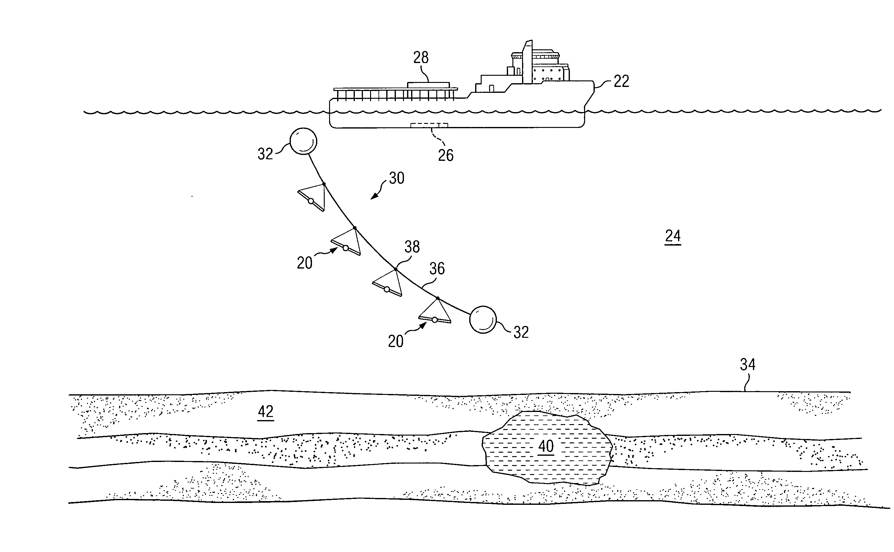
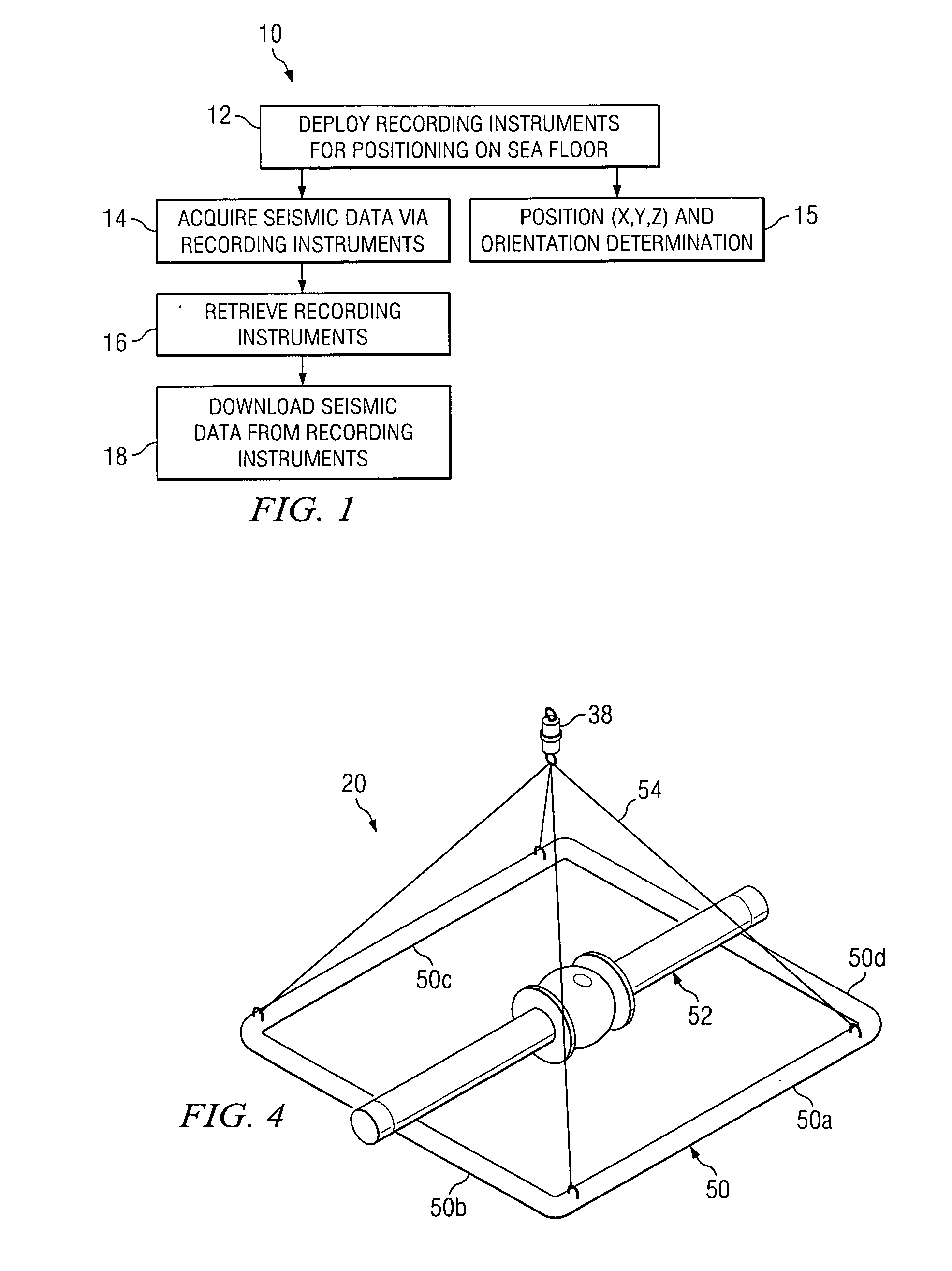
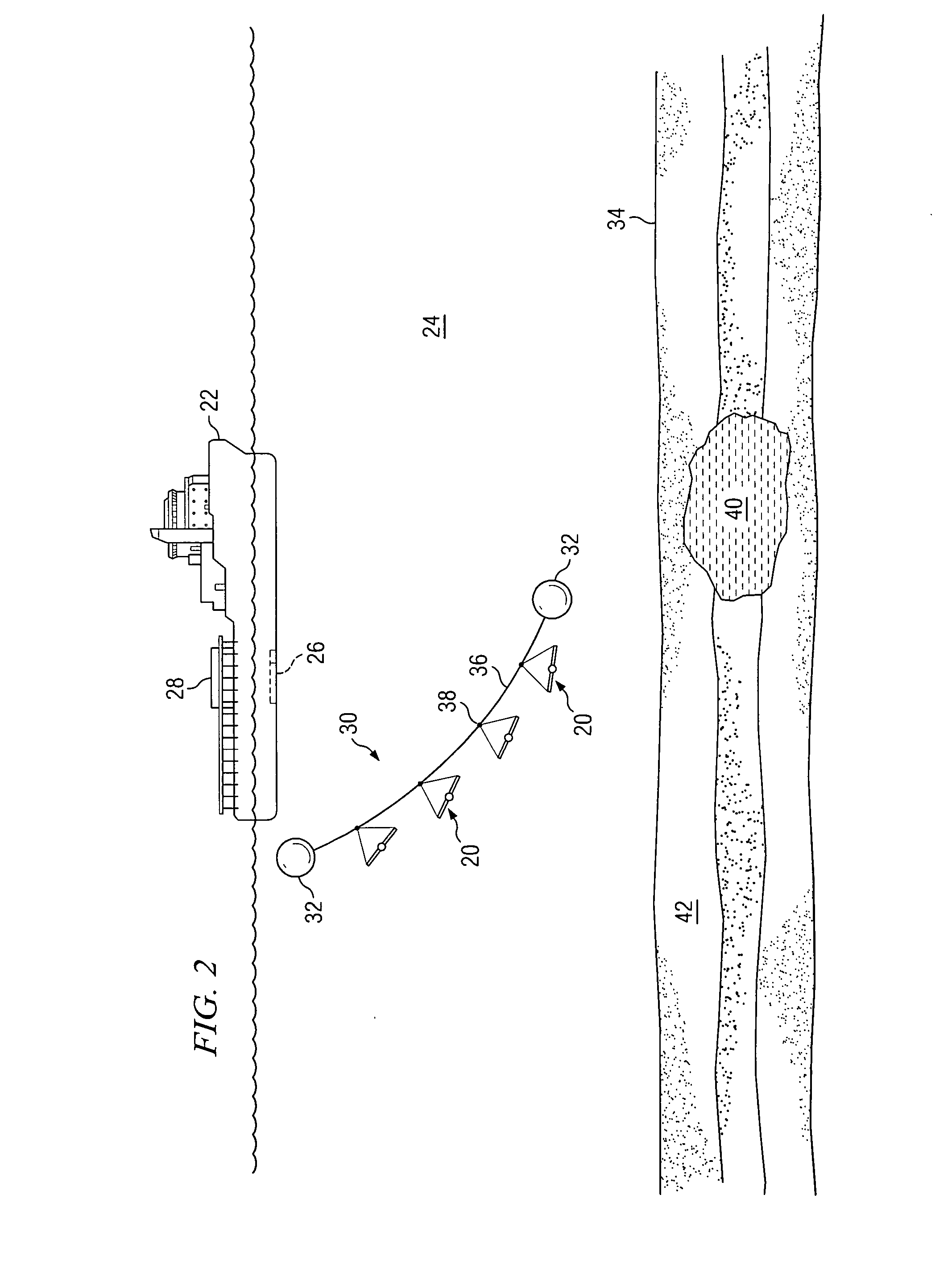
[0028]FIG. 1 illustrates a block diagram 10 depicting general steps for acquiring seismic data according to the present disclosure. In one embodiment, the seismic data acquisition process begins with the deployment of seafloor recording instruments to the seafloor 12. Once positioned on the seafloor, the recording instruments acquire seismic data via recorder devices 14 to be described. Also, the position (expressed in x, y, z coordinates) and orientation of the instruments 15 on the seafloor is determined according to processes to be described. After acquisition of seismic data, the recording instruments are retrieved from the seafloo...


PUM


Abstract

The present disclosure generally relates to systems and methods for acquiring seismic data. In one exemplary embodiment, a method for acquiring seismic data is described in which recorder instruments are deployed to the seafloor and utilized for recording pressure wave and shear wave data. An acoustic array, displaced from the seafloor, is also provided for sending acoustic signals to the instruments on the seafloor. The orientation of the instruments on the seafloor is determined via acoustic communication between the acoustic array and the instruments. Related systems and methods for acquiring seismic data are also described.

Description

CROSS-REFERENCE TO RELATED APPLICATIONS [0001] This application claims the benefit of U.S. Provisional Application No. 60 / 573,223, filed on May 21, 2004. U.S. Provisional Application No. 60 / 573,223 is commonly assigned with the present application and is hereby incorporated by reference for all purposes.TECHNICAL FIELD [0002] The present disclosure generally relates to seismic recording devices and systems, and methods for acquiring and conditioning seismic data. BACKGROUND [0003] Seismic data, such as pressure (P) wave and shear (S) wave data, is often used to model geological formations lying beneath the seafloor. Seismic data is particularly useful in the offshore energy industry to gain a better understanding of potential drill sites. For example, seismic data can be used to determine the existence of a fossil fuel reservoir, and whether such reservoir is capable of trapping such fuels by the existence of stratigraphic “traps” which prevent upward loss of the fluids. [0004] Vari...

Claims


Application Information

Patent Timeline
Patent Type & Authority Applications(United States)
IPC IPC(8): G01V1/20G01V1/38
CPCG01V1/201G01V1/38
Inventor SWANSON, MICHAEL
Owner ENTRE HLDG
Why Eureka
Try Eureka