Calibration method for exposure device, exposure method and exposure device

a technology of exposure device and calibration method, which is applied in the direction of microlithography exposure apparatus, instruments, electrographic process apparatus, etc., can solve the problems of alignment precision affecting (and deteriorating due), errors in alignment mark measurement, and deviation in exposure position relative to photosensitive materials, so as to improve the accuracy of correction of deviation in exposure position relative to the photosensitive material, the effect of improving the accuracy of correction of deviation

Inactive Publication Date: 2005-12-08
FUJIFILM CORP +1
View PDF5 Cites 32 Cited by
  • Summary
  • Abstract
  • Description
  • Claims
  • Application Information

AI Technical Summary

Benefits of technology

[0030] With the seventh embodiment of the present invention, the exposure position adjustment function of the exposure device is calibrateed. In order to do this, prior to reading a standard mark that is an exposure standard provided on a photosensitive material, a calibration component provided with multiple calibration standard marks arranged at preset intervals along the moving direction of a reading unit is placed in a position that is readable for the reading unit. The reading unit, placed in a position to read the above-described standard mark, reads a standard mark from among the multiple calibration standard marks. Calibration data is calculated based on the position data of the reading unit obtained by this reading. For example, in the case where the reading unit is a photographing device, the calibration data is calculated based on data such as position deviation data of the photographing optical axis (lens optical axis) and the calibration standard mark. That calibration data is reflected in the standard position data. Due to this, calibration of the exposure position adjustment fun

Problems solved by technology

When the alignment camera is moved, problems such as errors in the precision of the assembly and in each unit comprising the camera drive mechanism occur.
This type of position shift directly causes errors in alignment mark measurement.
Accordingly, even if image exposure is performed after correcting the exposure position using the above-described alignment function, the alignment precision is affected by (and deteriorates due to) the position change that accompanies movement of the alignment camera.
This is problematic in t

Method used


Image

  • Calibration method for exposure device, exposure method and exposure device
  • Calibration method for exposure device, exposure method and exposure device
  • Calibration method for exposure device, exposure method and exposure device

Examples


Embodiment Construction

[0054] Hereafter, the exposure device of the embodiments of the present invention will be explained while referring to the drawings.

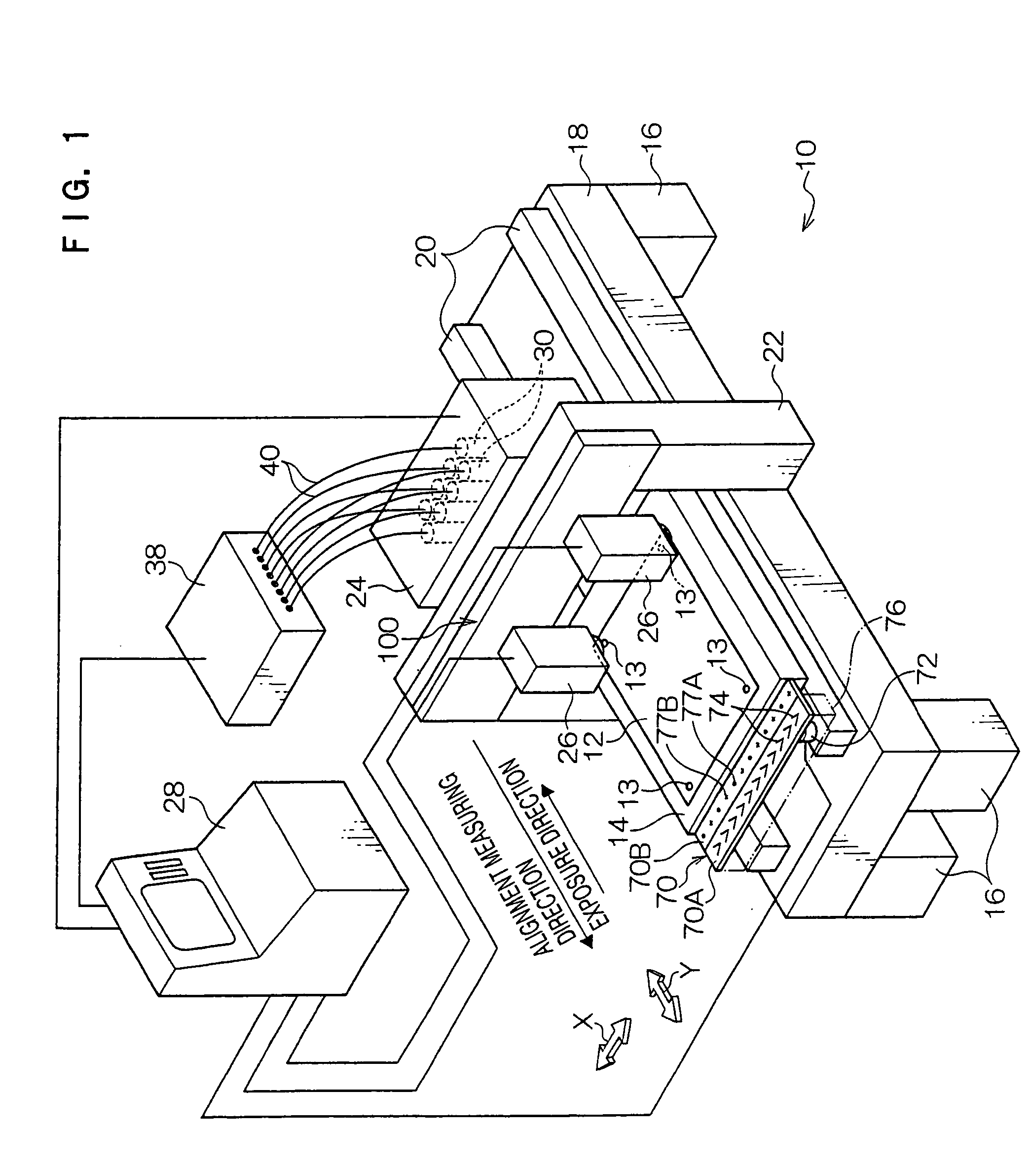
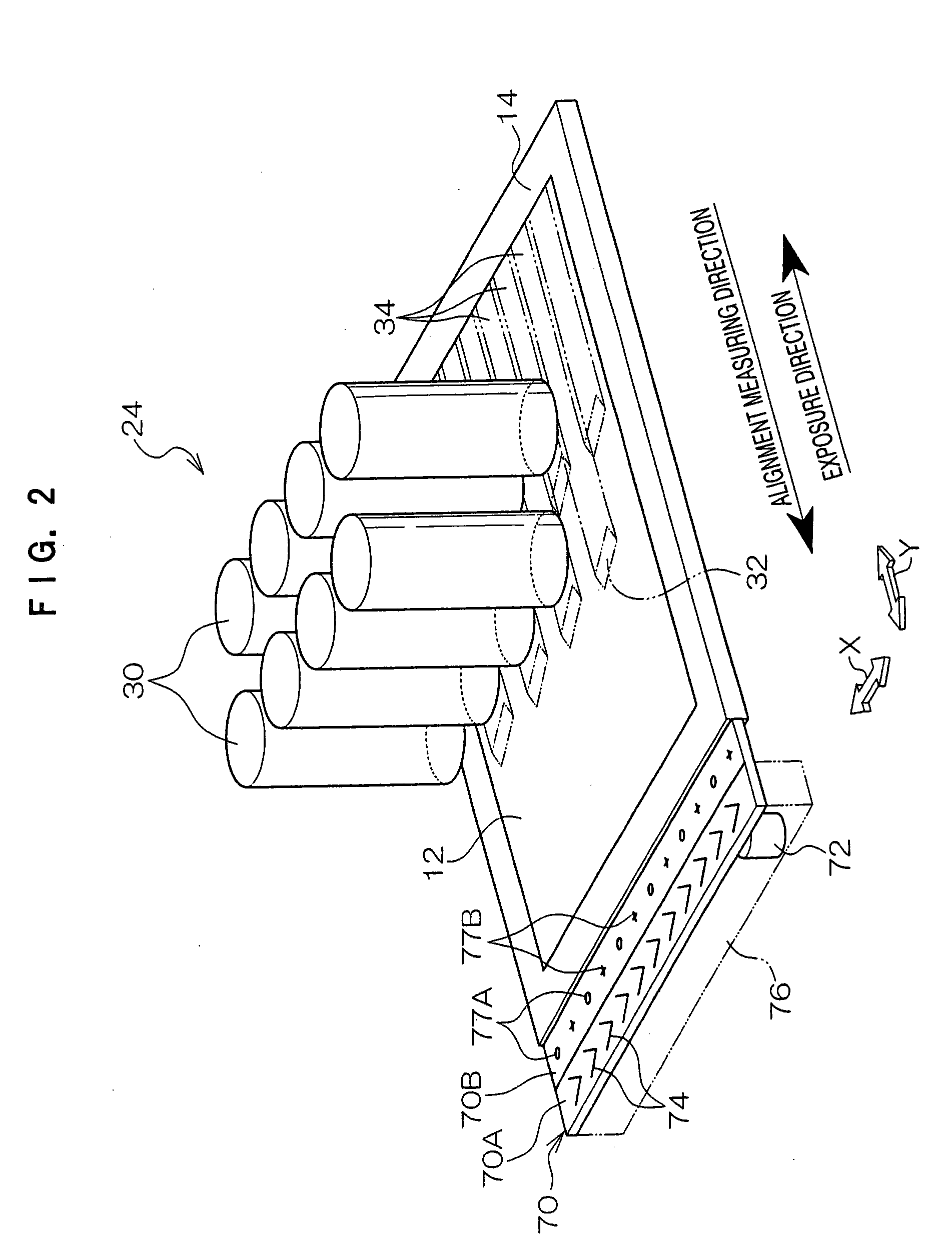
[0055] An embodiment of the exposure device of the present invention is illustrated in FIG. 1. Further, FIGS. 2 through 6 show an exposure head and SLM elements applied to embodiments of the present invention, and FIG. 7 shows an alignment unit as applied to an embodiment of the exposure device of the present invention.

[0056] As shown in FIG. 1, the exposure device 10 is equipped with a rectangular thick placement mount 18 supported by four legs 16. The upper surface of the placement mount 18 has two guides 20 extending in the lengthwise direction, and a rectangular stage 14 is provided on the two guides 20. The stage 14 forms the moving structure and is set to face the extending lengthwise direction of the guides 20, being supported such that it can move back and forth on the placement mount 18 via the guides 20. The stage 14 is driven by a drive mec...


PUM


Abstract

In this exposure system, alignment marks on a photosensitive material are photographed with a reading unit. Prior to this photographing, a standard board, having detection marks at positions readable to the reading unit at preset intervals along the movement direction of the reading unit, is provided. At least one of the detection marks is photographed with the reading unit, which is arranged in a position to photograph the alignment marks provided on the photosensitive material. Calibration data is calculated based on data on the camera optical axis deviation obtained by this photographing. Standard position data reflects the calibration data, whereby calibration of the exposure position adjustment function of the exposure device is performed.

Description

CROSS-REFERENCE TO RELATED APPLICATION [0001] This application claims priority under 35 U.S.C. 119 from Japanese Patent Application No. 2004-107120, the disclosure of which is incorporated by reference herein. BACKGROUND OF THE INVENTION [0002] 1. Field of the Invention [0003] The present invention relates to an exposure device and a calibration method for an exposure device. Specifically, the present invention relates to an exposure device and a calibration method in which an exposure device exposes a photosensitive material with light beams modulated with a spatial modulation element or the like in accordance with image data, and performs calibration with an exposure position adjustment function. [0004] 2. Description of the Related Art [0005] Conventionally, there have been various proposals for exposure devices, such as those that use the spatial light modulation elements (SLM) of devices such as digital micro-mirror devices (DMD). In these devices, image exposure is performed u...

Claims


Application Information

Patent Timeline
IPC IPC(8): G03F7/20G03G15/04G03G15/043
CPCG03G15/043G03G2215/04H01P1/2053H01P1/2084H01P7/06
Inventor UEMURA, HIROSHIFUKUDA, TAKESHI
Owner FUJIFILM CORP
Why Eureka
Try Eureka